Water Tower Sizing for a Pressurized Network
Context: Pressurized Water DistributionA network of pipes, tanks, and pumps that delivers water to consumers under pressure..
This exercise involves the preliminary design of an elevated water storage tank (a water tower) for a new residential subdivision. We must determine two critical parameters: the required height of the tank to ensure adequate pressure for all residents, and the total storage volume needed to meet daily demands and emergency (fire flow) requirements.
Pedagogical Note: This exercise will guide you through applying fundamental hydraulic principles (static head, friction loss) and understanding the key components of water demand (equalizing storage, fire storage) as per common US engineering standards.
Learning Objectives
- Understand and calculate Static HeadThe potential energy of water due to its elevation, often expressed in feet or psi. requirements.
- Apply the Hazen-Williams formulaAn empirical formula used in the US to calculate friction loss in pipes. to find head loss.
- Determine the total required storage volume based on equalization and fire flow.
- Analyze the system's Hydraulic Grade Line (HGL) under different demand conditions.
Study Data
System Specifications
| Characteristic | Value |
|---|---|
| Highest Service Connection Elevation | 150 ft |
| Minimum Required Service Pressure (at connection) | 40 psi |
| Water Main Material | Ductile Iron |
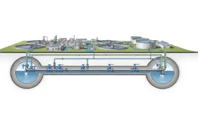
System Layout Schematic
| Parameter | Symbol | Value | Unit |
|---|---|---|---|
| Peak Hour Demand | \(Q_{\text{phd}}\) | 500 | GPM |
| Max Daily Demand (MDD) | \(Q_{\text{mdd}}\) | 1.2 | MGD |
| Required Fire Flow | \(Q_{\text{fire}}\) | 1500 | GPM |
| Fire Flow Duration | \(t_{\text{fire}}\) | 2 | hours |
| Pipe Length to Critical Point | \(L\) | 5000 | ft |
| Pipe Diameter | \(D\) | 12 | in |
| Hazen-Williams C-Factor | \(C\) | 140 | (New DI Pipe) |
Questions to Address
- What is the minimum water level (elevation) in the tower required to meet the 40 psi minimum pressure at the highest service connection, *ignoring friction loss* (i.e., under static conditions)?
- Using the Hazen-Williams formula, what is the head loss (\(h_f\)) in the 5000 ft main pipe during the Peak Hour Demand (500 GPM)?
- What is the new minimum water level (the Bottom Water Level, or BWL) required to maintain 40 psi during Peak Hour Demand (i.e., including static head and friction loss)?
- What is the total required storage volume for the tank, assuming it must provide Equalizing Storage (25% of MDD) and the full Fire Storage requirement?
- Synthesis: Based on your findings, state the key design parameters: the required Bottom Water Level (BWL) elevation and the Total Storage Volume.
Fundamentals of Pressurized Hydraulics
To solve this exercise, we will rely on two fundamental principles used in US water system design.
1. Static Head and Pressure Conversion
Pressure in a fluid at rest is caused by the weight of the fluid above it. In US customary units, the pressure (\(p\) in psi) and the height of the water column (\(h\) in feet) are related.
\[ p \text{ (psi)} = \frac{h \text{ (ft)}}{2.31} \quad \text{or} \quad h \text{ (ft)} = p \text{ (psi)} \times 2.31 \]
This means 2.31 feet of water height creates 1 psi of pressure.
2. Hazen-Williams Formula (Friction Loss)
As water flows through a pipe, energy is lost to friction. The Hazen-Williams formula is a common empirical method to calculate this head loss (\(h_f\)).
\[ h_f = 10.44 \times \frac{L}{D^{4.87}} \times \left(\frac{Q}{C}\right)^{1.85} \]
Where:
- \(h_f\) = Head loss in feet
- \(L\) = Pipe length in feet
- \(D\) = Pipe diameter in inches
- \(Q\) = Flow rate in Gallons Per Minute (GPM)
- \(C\) = Hazen-Williams roughness coefficient (e.g., 140 for new DI pipe)
Solution: Water Tower Sizing for a Pressurized Network
Question 1: Minimum Static Water Level
Principle
First, we find the head (height of water) needed to create 40 psi of pressure. Then, we add this pressure head to the elevation of the service connection to find the minimum water elevation in the tank.
Mini-Lesson
This calculation is an application of the basic hydrostatic equation (\(p = \gamma h\)), where \(\gamma\) (gamma) is the specific weight of water. The conversion factor 2.31 ft/psi is simply the inverse of the pressure exerted by one foot of water (0.433 psi/ft).
Pedagogical Note
Think of "pressure head" (\(h_p\)) as a form of energy. The water in the tower has potential energy due to its height. This energy is converted to pressure energy at the tap. The tower must be high enough to provide 40 psi worth of energy.
Norms
The American Water Works Association (AWWA) and many state standards (like the "Ten States Standards") recommend a minimum service pressure between 35 and 40 psi for normal conditions to ensure all fixtures (sinks, showers) operate correctly.
Formula(s)
We will use the pressure-to-head conversion and the static level formula.
Pressure Head
Static Water Level
Hypotheses
The primary assumption is that the water is *static* (no flow, \(Q=0\)). In a static system, there is no friction loss, so the pressure depends only on the elevation difference.
- The water is at rest (no demand).
- The density of water is constant.
Data
From the problem statement:
| Parameter | Symbol | Value | Unit |
|---|---|---|---|
| Required Pressure | \(p_{\text{req}}\) | 40 | psi |
| Service Elevation | \(\text{Elev}_{\text{service}}\) | 150 | ft |
Tips
Memorize the conversion: 2.31 ft = 1 psi. It's one of the most common constants in American water system design. Always add pressure head *on top of* the service elevation.
Schematic (Before Calculations)
A simple visual representation of the problem for this step.
Static Head Concept
Calculation(s)
Step 1: Calculate the pressure head (\(h_p\)) corresponding to 40 psi. We use the conversion \(h_p = p \times 2.31\).
This result means that a 92.4-foot tall column of water is required to produce 40 psi of pressure.
Step 2: Add this pressure head to the service elevation to find the total static water level (\(\text{Elev}_{\text{TWL}}\)).
Therefore, the water surface in the tower must be at an elevation of 242.4 ft, assuming no water is flowing.
Schematic (After Calculations)
The same visual, now with the calculated values filled in.
Static Head Result
Analysis
Under static (no-flow) conditions, the water level in the tower must be at an elevation of at least 242.4 ft to provide the bare minimum pressure to the highest customer.
Cautionary Points
This is the absolute minimum level. This calculation is incomplete for a real system because it ignores friction loss. As soon as water starts flowing, the pressure will drop below 40 psi.
Key Takeaways
- Pressure is directly related to water height (head).
- The static level is the baseline for design; all losses are *added* to this.
Did You Know?
Large cities are often divided into "pressure zones." Each zone is served by its own set of pumps or towers to ensure pressure isn't too high (at low elevations) or too low (at high elevations).
FAQ
Common questions about this step.
Final Result
Your Turn
If the minimum required pressure was 50 psi, what would the static TWL elevation be?
Memo Card
Question 1 Summary:
- Key Concept: Static Head
- Essential Formula: \(\text{Elev}_{\text{TWL}} = \text{Elev}_{\text{service}} + (p_{\text{req}} \times 2.31)\)
- Key Data: \(\text{Elev} = 150 \text{ ft}, p = 40 \text{ psi}\)
Question 2: Head Loss during Peak Hour Demand (500 GPM)
Principle
We will apply the Hazen-Williams formula directly using the provided data to find the head loss (\(h_f\)) caused by friction when 500 GPM is flowing through the pipe.
Mini-Lesson
The Hazen-Williams formula is an *empirical* equation, meaning it's based on experimental data, not pure theory. Notice that flow (\(Q\)) is to the 1.85 power, and diameter (\(D\)) is to the 4.87 power. This means head loss is very sensitive to flow rate (doubling flow roughly triples loss) and *extremely* sensitive to diameter (halving diameter increases loss by ~29x).
Pedagogical Note
This formula (Hazen-Williams) is standard practice for water distribution in the US. A more theoretically rigorous formula is the Darcy-Weisbach equation, which is common in other fields of engineering (like petroleum) and in Europe. H-W is popular because the C-Factor is relatively constant for the flow rates seen in water systems.
Norms
The C-Factor of 140 is for new, cement-lined Ductile Iron Pipe (DI). AWWA standards (like C151) specify materials. Designers often use a lower C-Factor (e.g., 120-130) to account for aging and tuberculation (pipe interior buildup) over the 20-50 year life of the pipe.
Formula(s)
This is the standard Hazen-Williams formula for head loss in US customary units.
Hypotheses
To use this formula, we assume several things:
- The flow is fully turbulent (which is true for this Q and D).
- The water temperature is around 60°F (as the C-Factor depends on viscosity).
- Minor losses (from bends, valves, etc.) are negligible compared to the friction loss over the 5000 ft length.
Data
| Parameter | Symbol | Value | Unit |
|---|---|---|---|
| Length | \(L\) | 5000 | ft |
| Diameter | \(D\) | 12 | in |
| Flow Rate | \(Q\) | 500 | GPM |
| C-Factor | \(C\) | 140 |
Tips
The Hazen-Williams formula is unit-specific! It *only* works if you use Length in feet, Diameter in inches, and Flow in GPM. Mixing these up (e.g., using 1 ft for diameter) is the most common mistake.
Schematic (Before Calculations)
A simple representation of the pipe section being analyzed.
Pipe Friction Loss
Calculation(s)
Step 1: Write the full Hazen-Williams formula.
Step 2: Substitute the known values from the data table: L=5000, D=12, Q=500, C=140.
Step 3: To make this easier, let's calculate the value of each main component of the equation:
This shows the diameter term is 18914, the flow term is 10.15, and the length/constant term is 52200.
Step 4: Combine these intermediate results to find the final head loss, \(h_f\).
The total head loss due to friction over the 5000 ft pipe is 27.98 ft.
Schematic (After Calculations)
This shows the "Hydraulic Grade Line" (HGL), the line of energy, dropping due to friction.
Head Loss Result
Analysis
This 28.0 ft loss is the "friction penalty" for moving 500 GPM through 5000 ft of pipe. This energy is lost as heat. It means the water tower must be 28.0 ft *higher* than the static calculation (Q1) to overcome this loss and still deliver 40 psi.
Cautionary Points
This calculation is for Peak Hour Demand. The head loss during the 1500 GPM Fire Flow will be *much* higher (approx. 210.5 ft, as seen in the Q3 "Your Turn"). A real design must check both scenarios.
Key Takeaways
- Friction loss is a major component of hydraulic design.
- Head loss increases non-linearly (power of 1.85) with flow rate.
Did You Know?
The Hazen-Williams formula was first published in 1905 by engineers Allen Hazen and Gardner S. Williams. It is still the most common formula used in municipal water design in the US today.
FAQ
Common questions about this step.
Final Result
Your Turn
What would the head loss be if the pipe was old and rough (C = 100)?
Memo Card
Question 2 Summary:
- Key Concept: Friction Loss (Hazen-Williams)
- Essential Formula: \(h_f = 10.44 \times (L/D^{4.87}) \times (Q/C)^{1.85}\)
- Key Data: \(L=5000, D=12, Q=500, C=140\)
Question 3: Minimum Dynamic Water Level (BWL)
Principle
The water tower must provide the static head (from Q1) *plus* the energy to overcome friction loss (from Q2). This new, higher level is the minimum elevation the water can be during normal operation, known as the Bottom Water Level (BWL).
Mini-Lesson
This illustrates the concept of the Hydraulic Grade Line (HGL). The HGL represents the total energy (elevation + pressure) at any point. The water level in the tower *is* the HGL at the start. The HGL at the service connection must be \(\text{Elev} + h_p = 150 \text{ ft} + 92.4 \text{ ft} = 242.4 \text{ ft}\). The tower's HGL must be high enough to account for the drop: \(\text{HGL}_{\text{start}} = \text{HGL}_{\text{end}} + h_f\).
Pedagogical Note
Always design for the "critical point." This is the location in the system that is hardest to serve. It's typically the point with the highest elevation, the farthest distance (most friction), or a combination of both. Here, we assume the 150 ft elevation is the critical point.
Norms
"Ten States Standards" (a common guideline for US water systems) often specifies a minimum pressure of 20 psi during *fire flow* conditions. The 40 psi we are using is for *normal* (Peak Hour) conditions. A full design would check both and pick the higher required BWL.
Formula(s)
Full Formula
The BWL is the elevation of the service point, plus the pressure head needed *at* that point, plus all the head losses *between* the tower and that point.
Using Q1 Result:
Since we calculated \(\text{Elev}_{\text{Static}} = \text{Elev}_{\text{service}} + h_p\) in Question 1, we can simplify this.
Hypotheses
We are assuming that the Peak Hour Demand (500 GPM) at 40 psi is the *critical scenario* that sets the BWL, not the fire flow (1500 GPM) at 20 psi. This is a common assumption, but must be checked.
- The Peak Hour demand is the critical design case for minimum pressure.
Data
| Parameter | Symbol | Value | Unit |
|---|---|---|---|
| Static Level (from Q1) | \(\text{Elev}_{\text{Static}}\) | 242.4 | ft |
| Head Loss (from Q2) | \(h_f\) | 28.0 | ft |
Tips
A common mistake is subtracting friction loss. Visualize it: The HGL *starts* at the tower and *drops* down to the customer. The *end* point (242.4 ft) must be met. Therefore, the *start* point must be higher: \(\text{Start} = \text{End} + \text{Loss}\).
Schematic (Before Calculations)
The full system, showing all energy components.
Dynamic Head (HGL) Concept
Calculation(s)
We use the simplified formula for the dynamic water level (BWL), substituting the results from Question 1 (\(\text{Elev}_{\text{Static}}\)) and Question 2 (\(h_f\)).
This new elevation of 270.4 ft is the minimum level the water can be in the tank to ensure 40 psi at the tap *during* peak flow.
Schematic (After Calculations)
The full HGL diagram with all elevations labeled.
Dynamic Head (HGL) Result
Analysis
The bottom of the usable water in the tank must be at an elevation of 270.4 ft. Any lower, and the highest customer will receive less than 40 psi during peak demand.
Cautionary Points
This BWL *only* works if the C-factor remains 140. If the pipe ages (C=100), the head loss at 500 GPM would be 52.4 ft (from Q2 'Your Turn'). The pressure at the tap would drop to \((270.4 - 52.4 - 150) / 2.31 = 29.4 \text{ psi}\), which is below the minimum requirement!
Key Takeaways
- The dynamic water level (BWL) is set by the static head *plus* friction losses.
- The BWL is a critical design parameter that sets the tank's height.
Did You Know?
Some cities, like Chicago, are so flat they don't use water towers. They rely entirely on "direct pressure" from pumping stations, which must run 24/7 to maintain pressure in the lines.
FAQ
Common questions about this step.
Final Result
Your Turn
What would the BWL need to be to handle the required fire flow (\(Q_{\text{fire}}\) = 1500 GPM), assuming the head loss at that flow is 210.5 ft *and* the minimum pressure is 20 psi?
Memo Card
Question 3 Summary:
- Key Concept: Dynamic Head (HGL)
- Essential Formula: \(\text{BWL} = \text{Elev}_{\text{Static}} + h_f\)
- Key Data: \(\text{Elev}_{\text{Static}} = 242.4 \text{ ft}, h_f = 28.0 \text{ ft}\)
Question 4: Total Required Storage Volume
Principle
The total storage volume is the sum of all storage components. For this exercise, we'll sum the Equalizing Storage (to meet demand fluctuations) and the Fire Storage (for emergencies).
Mini-Lesson
Equalizing Storage (\(V_{\text{eq}}\)): Volume needed to "equalize" the difference between the constant pump supply rate and the variable hourly demand. It's often estimated as 20-25% of the Max Daily Demand (MDD).
Fire Storage (\(V_{\text{fire}}\)): Volume required to fight a fire for a specific duration. It is calculated as \(Q_{\text{fire}} \times t_{\text{fire}}\).
Pedagogical Note
These two volumes are "stacked" in the tank. The BWL (270.4 ft) is the floor. The Top Water Level (TWL) is the elevation of the BWL *plus* the water depth required to store 480,000 gallons. The tank is then designed to cycle between the TWL and a level *above* the fire storage volume.
Norms
Fire flow (1500 GPM for 2 hours) is a typical requirement for a small residential area, often set by the Insurance Services Office (ISO) or local fire code. ISO ratings can affect the fire insurance rates for all homeowners in the development.
Formula(s)
Equalizing Storage
Fire Storage
Total Storage
Hypotheses
We make two key assumptions for this simplified calculation:
- The 25% of MDD rule is a sufficient, state-approved estimate. (A more detailed design would use a "mass curve analysis" of hourly demands vs. pumping).
- The required fire flow and the peak hour demand do not occur at the same time.
Data
| Parameter | Symbol | Value | Unit |
|---|---|---|---|
| Max Daily Demand | \(Q_{\text{mdd}}\) | 1,200,000 | gal |
| Equalizing % | 25 | % | |
| Fire Flow | \(Q_{\text{fire}}\) | 1500 | GPM |
| Fire Duration | \(t_{\text{fire}}\) | 2 | hours |
Tips
Units are critical! `1 MGD = 1,000,000 gallons`. `1 hour = 60 minutes`. Write out the unit conversions to avoid simple math errors. \(Q_{\text{fire}}\) is in GPM (Gallons Per *Minute*), but duration is in *Hours*.
Schematic (Before Calculations)
A diagram showing the components of storage in a tank.
Storage Volume Components
Calculation(s)
Step 1: Calculate the Equalizing Storage (\(V_{\text{eq}}\)) as 25% of the Max Daily Demand (MDD).
The volume needed to balance daily demand is 300,000 gallons.
Step 2: Calculate Fire Storage (\(V_{\text{fire}}\)). We must convert units from GPM and hours to total gallons.
The volume needed for a 2-hour fire is 180,000 gallons.
Step 3: Calculate Total Storage (\(V_{\text{total}}\)) by summing the components.
The total usable storage required in the tank is 480,000 gallons.
Schematic (After Calculations)
The same tank, now with the calculated volumes labeled.
Storage Volume Results
Analysis
The tank will be specified with a minimum usable capacity of 480,000 gallons. This means the *usable* range (the volume between the BWL and the Top Water Level, TWL) must contain this volume.
Cautionary Points
This volume does not include "dead storage" — the unusable water at the very bottom of the tank below the outlet pipe, which is needed for sediment. The actual physical tank will be slightly larger to account for this.
Key Takeaways
- Total volume is the sum of all required components (Equalization, Fire, Emergency).
- Fire flow requirements are often a massive part of the total volume.
Did You Know?
To prevent water from going stale and losing chlorine residual, modern tanks have complex internal mixing systems (e.g., "baffles" or "nozzles") to ensure water is constantly circulated as the tank fills and drains.
FAQ
Common questions about this step.
Final Result
Your Turn
If the required fire duration was 3 hours instead of 2, what would the new *total* volume be?
Memo Card
Question 4 Summary:
- Key Concept: Storage Volume Components
- Essential Formula: \(V_{\text{total}} = V_{\text{eq}} + V_{\text{fire}}\)
- Key Data: \(MDD=1.2\text{MGD}, Q_{\text{fire}}=1500\text{GPM}, t_{\text{fire}}=2\text{hr}\)
Question 5: Synthesis of Design Parameters
Principle
This step synthesizes the key findings from the previous questions into a final set of design recommendations for the water tower.
Analysis
We have determined the two primary design parameters for the tank:
Conclusion: The engineering design recommendation would be to specify an elevated tank with a Bottom Water Level (BWL) at 270.4 ft and a total storage capacity of 480,000 gallons.
Final Result
Your Turn
If the tower's foundation is built on ground at an elevation of 180 ft, what is the minimum *structural height* of the tower (from the foundation to the BWL)?
Interactive Tool: Hydraulic Grade Line (HGL) Simulator
Use the sliders to see how flow rate and pipe roughness (C-Factor) affect the head loss and the final pressure delivered to the service connection. The BWL is fixed at 270.4 ft.
Input Parameters
Key Requirements
Final Quiz: Test Your Knowledge
1. "Static Head" refers to:
2. In the Hazen-Williams formula, a *lower* C-Factor (e.g., C=100) means the pipe is:
3. If you *increase* the flow rate (GPM) in a pipe, the friction loss (\(h_f\)) will:
Glossary
- Bottom Water Level (BWL)
- The lowest allowable water elevation in a storage tank during normal operation, set to maintain minimum system pressure.
- Equalizing Storage
- The volume of water in a tank used to buffer the difference between the (often constant) inflow/pumping rate and the (variable) hourly water demand.
- Fire Storage
- The volume of water reserved in a tank specifically for emergency fire-fighting purposes.
- GPM (Gallons Per Minute)
- A unit of flow rate commonly used in the United States.
- Hazen-Williams C-Factor
- An empirical coefficient representing the smoothness or roughness of a pipe's interior. A high C-Factor (e.g., 140) means a smooth pipe with low friction. A low C-Factor (e.g., 100) means a rough pipe with high friction.
- Head Loss (\(h_f\))
- The energy (expressed as a height of water in feet) lost from the system due to friction as water flows through pipes.
- Hydraulic Grade Line (HGL)
- An imaginary line showing the elevation to which water would rise in an open tube attached to a pressurized pipe. It represents the sum of elevation head and pressure head.
- MGD (Million Gallons per Day)
- A unit of total water volume used over a 24-hour period.
- psi (Pounds per Square Inch)
- A unit of pressure commonly used in the United States. 1 psi is the pressure created by a 2.31-foot column of water.
- Static Head
- The potential energy of water due to its elevation, representing the pressure in a fluid at rest.
0 Comments