Sizing a Hydraulic Power Unit Reservoir
Context: Hydraulic Reservoir DesignThe process of selecting a tank that holds hydraulic fluid, provides cooling, and allows for system component mounting..
This exercise covers the design process for a hydraulic reservoir (or tank) for a fluid power unit. Proper sizing is critical for system longevity, thermal management, and efficiency. A reservoir does more than just hold fluid; it helps cool the oil, separate air and water, and allows contaminants to settle. We will size a reservoir for a hydraulic press application based on US industry standards.
Pedagogical Note: This exercise will teach you to apply industry rules of thumb (using US customary units) and fundamental heat transfer calculations to select a practical, standard-sized reservoir.
Learning Objectives
- Apply the 3-5x flow rate rule for initial volume sizing.
- Calculate the required reservoir surface area for heat dissipation.
- Select a standard reservoir size and verify its specifications.
- Understand the trade-offs between reservoir size and the need for external cooling.
Study Data
System Specifications
| Characteristic | Value |
|---|---|
| System Type | Hydraulic Press (Intermittent Duty) |
| Pump Type | Fixed Displacement Vane Pump |
| Governing Standard | ANSI/NFPA T3.16.2 R1-2010 (Recommended Practice for the Design, Care, and Safety of HPU's) |
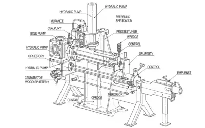
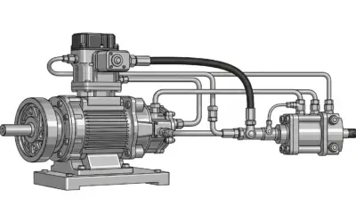
Basic Hydraulic Power Unit (HPU) Schematic
| Parameter | Symbol | Value | Unit |
|---|---|---|---|
| Pump Flow Rate | \(Q_{\text{p}}\) | 15 | \(\text{GPM}\) |
| System Pressure | \(P_{\text{sys}}\) | 2500 | \(\text{PSI}\) |
| Estimated Heat Load | \(H_{\text{load}}\) | 2 | \(\text{HP}\) |
| Ambient Temperature | \(T_{\text{amb}}\) | 80 | \(\text{°F}\) |
| Max Fluid Temperature | \(T_{\text{max}}\) | 140 | \(\text{°F}\) |
Questions to Address
- Calculate the minimum recommended reservoir volume (\(V_{\text{min}}\)) in gallons, using the 3x rule of thumb.
- Calculate the required reservoir surface area (\(A_{\text{req}}\)) in \(\text{ft}^2\) for heat dissipation.
- A standard 40-gallon "L-Shape" reservoir is proposed. Its dimensions provide a total surface area of 18 \(\text{ft}^2\). Is this *area* sufficient?
- Calculate the *actual* heat dissipation (\(H_{\text{diss}}\)) in \(\text{HP}\) for the proposed 40-gallon reservoir (with 18 \(\text{ft}^2\) area).
- Based on all factors (volume rule, heat dissipation), is the proposed 40-gallon reservoir a suitable choice? Justify your answer.
Fundamentals of Reservoir Sizing
Two primary considerations drive reservoir sizing: adequate fluid volume and heat dissipation. Both must be satisfied for a reliable system.
1. Volume Rule of Thumb (US Customary)
For standard industrial systems, the reservoir volume (in gallons) should be 3 to 5 times the pump flow rate (in \(\text{GPM}\)).
\[ V_{\text{res}} = (3 \text{ to } 5) \times Q_{\text{p}} \]
A 3x rule is often acceptable for intermittent systems with known heat loads, while 5x is safer for continuous-duty systems.
2. Heat Dissipation (US Customary)
The reservoir dissipates heat through its walls (surface area). The rate is based on its area and the temperature difference between the oil and the surrounding air.
\[ H_{\text{diss}} = K \times A \times (T_{\text{fluid}} - T_{\text{amb}}) \]
Where \(K\) is a heat transfer coefficient. For a standard reservoir in still air, a conservative value is \(K \approx 0.001 \text{ HP} / (\text{ft}^2 \cdot \text{°F})\).
Solution: Sizing a Hydraulic Power Unit Reservoir
Question 1: Calculate the minimum recommended reservoir volume (\(V_{\text{min}}\)) in gallons, using the 3x rule of thumb.
Principle
This rule ensures there is enough fluid (residence time) for the system to operate smoothly, allow contaminants to settle, and permit entrained air to be released from the fluid before it re-enters the pump.
Mini-Lesson
The "3-to-5x" rule is a starting point. Since our application is a hydraulic press (intermittent duty), using the 3x minimum rule is a common and acceptable starting point. If this were a 24/7 continuous-duty system, we would start with the 5x rule.
Pedagogical Note
Think of this rule as the "storage" requirement. We first determine how much fluid we need to *hold*, and then we check if the container is large enough to *cool* that fluid. Both must be true.
Norms
ANSI/NFPA standards (like T3.16.2) provide guidelines for reservoir *construction* (e.g., baffles, clean-outs, air gap, fluid level indicators), which complement this initial sizing rule.
Formula(s)
The formula for the minimum recommended volume based on the 3x rule is:
Hypotheses
We assume the 3x rule is appropriate for this intermittent-duty application. We also assume the \(\text{GPM}\) value provided is the maximum flow rate of the pump(s).
- System is intermittent duty.
Data
We only need the pump flow rate for this question.
| Parameter | Symbol | Value | Unit |
|---|---|---|---|
| Pump Flow RateThe volume of fluid moved by the pump per unit of time. | \(Q_{\text{p}}\) | 15 | \(\text{GPM}\) |
Tips
Always double-check if your system has multiple pumps. If so, \(Q_{\text{p}}\) is typically the *sum* of all pump flow rates.
Schematic (Before Calculations)
This calculation is a direct application of the formula using the data provided in the problem statement.
Rule of Thumb Calculation
Calculation(s)
We apply the 3x rule to the given pump flow rate.
Step 1: Apply the formula
Here, we substitute the \(Q_{\text{p}}\) value (15 \(\text{GPM}\)) from our data table into the formula \(V_{\text{min}} = 3 \times Q_{\text{p}}\).
The result of the calculation (3 times 15) is 45. This means our minimum required volume is 45 gallons.
Analysis
The minimum *recommended* volume based on standard industry practice is 45 gallons. This provides a baseline for our selection. Any reservoir we consider should ideally be at least this large.
Key Takeaways
- The 3x-5x rule is the *first step* in reservoir sizing.
- This rule is based on pump flow rate, not pressure or horsepower.
Did You Know?
For *mobile* hydraulic systems (like on a bulldozer or crane), this rule is ignored. Mobile reservoirs are often sized as small as 0.5x to 1x the pump flow rate to save space and weight.
FAQ
Common questions for this step.
Final Result
Your Turn
What would the *maximum* recommended volume be, using the 5x "continuous duty" rule?
Memo Card
Question 1 Summary:
- Key Concept: Volume Rule of Thumb.
- Essential Formula: \(V_{\text{min}} = 3 \times Q_{\text{p}}\).
- Key Data: \(Q_{\text{p}} = 15 \text{ GPM}\).
Question 2: Calculate the required reservoir surface area (\(A_{\text{req}}\)) in \(\text{ft}^2\) for heat dissipation.
Principle
The reservoir must act as a radiator. It dissipates the system's waste heat (from inefficiencies) to the surrounding air. We must calculate the minimum surface area needed to get rid of this heat to prevent the oil from overheating.
Mini-Lesson
Heat transfer from a tank is complex, but for standard industrial estimates, a simplified formula is used. The \(K\) factor combines convection and radiation. The larger the temperature difference (\(\Delta T\)) between the oil and the air, the more heat will be dissipated for a given area.
Pedagogical Note
This calculation determines if the tank can *cool itself* (passive cooling). If the required area is impractically large, it signals that an *active* cooling solution (like an oil cooler with a fan or water) will be necessary.
Norms
The heat transfer coefficient \(K \approx 0.001 \text{ HP} / (\text{ft}^2 \cdot \text{°F})\) is a widely accepted empirical value (rule of thumb) in the US fluid power industry for standard steel reservoirs in still air.
Formula(s)
We start with the heat dissipation formula and rearrange it to solve for the required Area (\(A_{\text{req}}\)).
Base Formula
Rearranged for Required Area
Hypotheses
We assume the heat load is constant at 2 \(\text{HP}\). We assume the \(K\) factor is 0.001. We assume the only cooling mechanism is the reservoir walls (no external cooler).
- Steady-state heat load of 2 \(\text{HP}\).
- Heat transfer is only via reservoir walls.
Data
We need all the thermal data from the problem statement.
| Parameter | Symbol | Value | Unit |
|---|---|---|---|
| Heat Load | \(H_{\text{load}}\) | 2 | \(\text{HP}\) |
| Heat Transfer Coeff. | \(K\) | 0.001 | \(\text{HP} / (\text{ft}^2 \cdot \text{°F})\) |
| Max Fluid Temp | \(T_{\text{max}}\) | 140 | \(\text{°F}\) |
| Ambient Temp | \(T_{\text{amb}}\) | 80 | \(\text{°F}\) |
Tips
The most common error is miscalculating \(\Delta T\). It's always (Fluid Temp - Ambient Temp). If this value is small, the required area will become very large, very quickly!
Schematic (Before Calculations)
This diagram shows the concept: heat *generated* by the HPU must be *dissipated* by the tank's surface area to maintain a stable temperature.
Heat Balance Concept
Calculation(s)
We must first find the temperature difference (\(\Delta T\)) and then solve for \(A_{\text{req}}\).
Step 1: Calculate the temperature differential (\(\Delta T\))
First, we find the temperature difference (\(\Delta T\)) by subtracting the ambient temperature (80\(\text{°F}\)) from the maximum allowed fluid temperature (140\(\text{°F}\)).
This gives us a temperature differential (\(\Delta T\)) of 60\(\text{°F}\). This is the "driving force" for our heat transfer.
Step 2: Calculate the required area
Now, we substitute our known values: \(H_{\text{load}}\) (2 \(\text{HP}\)), \(K\) (0.001), and our calculated \(\Delta T\) (60\(\text{°F}\)) into the rearranged formula.
The calculation (2 divided by 0.06) shows we need a minimum surface area of 33.33 square feet to dissipate the 2 \(\text{HP}\) of heat.
Analysis
To dissipate 2 \(\text{HP}\) of heat naturally, we need a reservoir with at least 33.33 \(\text{ft}^2\) of surface area exposed to the air. This is a *separate* requirement from the 45-gallon volume. We must satisfy *both*.
Cautionary Points
A common mistake is to only calculate the area of the tank *sides*. You must include all surfaces exposed to air, including the *top* of the reservoir, as it all contributes to cooling.
Key Takeaways
Heat dissipation is often the *driving* factor in reservoir sizing, more so than the volume rule, especially in high-power or continuous-duty systems.
Did You Know?
Painting a reservoir a dark, matte color (like black) can slightly increase its ability to radiate heat (increase the \(K\) value) compared to a light or glossy color.
FAQ
Common questions for this step.
Final Result
Your Turn
What area would be needed if the ambient temperature in the plant was 100\(\text{°F}\) instead of 80\(\text{°F}\)?
Memo Card
Question 2 Summary:
- Key Concept: Heat Dissipation.
- Essential Formula: \(A_{\text{req}} = H_{\text{load}} / (K \times \Delta T)\).
- Key Data: \(H_{\text{load}}=2 \text{ HP}, \Delta T=60 \text{ °F}\).
Question 3: A standard 40-gallon "L-Shape" reservoir is proposed. Its dimensions provide a total surface area of 18 \(\text{ft}^2\). Is this *area* sufficient?
Principle
This is a simple comparison step. We compare the *proposed* specifications of a real-world tank to the *required* specifications we just calculated.
Mini-Lesson
In engineering design, you first calculate theoretical *requirements* (like in Q1 and Q2). Then, you search for standard, off-the-shelf *components*. Finally, you must *verify* that the component you found meets or exceeds *all* your requirements.
Pedagogical Note
This step highlights a real-world problem. A 40-gallon tank *seems* close to our 45-gallon (Q1) requirement, so it might be tempting to choose it. But we *must* check *all* criteria. Here, we are checking the *area* criterion.
Norms
There are no specific standards for this step, it is a fundamental design verification principle: "Is the proposed part's capability >= the system's requirement?"
Formula(s)
Verification Check
Hypotheses
We assume the manufacturer's stated surface area of 18 \(\text{ft}^2\) is accurate and represents the external area exposed to the air.
- Manufacturer data is correct.
Data
We are comparing our calculated requirement from Q2 against the proposed tank's data.
| Parameter | Symbol | Value | Unit |
|---|---|---|---|
| Required Area (from Q2) | \(A_{\text{req}}\) | 33.33 | \(\text{ft}^2\) |
| Proposed Tank Area | \(A_{\text{prop}}\) | 18 | \(\text{ft}^2\) |
Tips
When looking at catalogs, "L-Shape" reservoirs are common. They are designed to have the pump and motor mounted on *top* of the tank, saving floor space. A flat "Rectangular" tank of the same volume would have more surface area but take up more space.
Schematic (Before Calculations)
Visually comparing the required area versus the provided area.
Area Comparison: Required vs. Proposed
Calculation(s)
No complex calculation is needed, just a direct comparison. We compare the value for \(A_{\text{prop}}\) (given in the question) to the value for \(A_{\text{req}}\) (which we calculated in Question 2).
Comparison
We place the proposed area (18 \(\text{ft}^2\)) next to the required area (33.33 \(\text{ft}^2\)) to check if it is sufficient.
This inequality shows that the proposed area is *less than* the required area. Therefore, the proposed tank fails this check.
Analysis
The proposed reservoir's surface area (18 \(\text{ft}^2\)) is **not sufficient**. It is significantly less than the 33.33 \(\text{ft}^2\) we calculated is needed to dissipate 2 \(\text{HP}\) of heat. This tank would overheat.
Cautionary Points
Do not confuse reservoir *volume* (gallons) with *surface area* (\(\text{ft}^2\)). A 40-gallon tank can have many different shapes (tall and skinny vs. short and wide). A tall, skinny tank will have less cooling capacity than a flat, wide tank of the same volume.
Key Takeaways
A component must meet *all* requirements. This tank is being checked for *area*, not volume (which we will check in Q5).
Did You Know?
Some special reservoirs are built with finned walls, like a radiator, to increase their surface area (\(A\)) without increasing their overall size or volume, improving the \(K\) value.
FAQ
Common questions for this step.
Final Result
Your Turn
How many *more* square feet of area are needed (what is the deficit)?
Memo Card
Question 3 Summary:
- Key Concept: Verification.
- Logic: Is \(A_{\text{prop}} \ge A_{\text{req}}\)?
- Result: No (18 < 33.33).
Question 4: Calculate the *actual* heat dissipation (\(H_{\text{diss}}\)) in \(\text{HP}\) for the proposed 40-gallon reservoir (with 18 \(\text{ft}^2\) area).
Principle
We use the same heat transfer formula from Q2, but this time we solve for \(H\) (Heat) using the *actual* area of the proposed tank (18 \(\text{ft}^2\)). This will tell us how much heat the tank *can* get rid of, which we can compare to the 2 \(\text{HP}\) the system *creates*.
Mini-Lesson
This calculation answers the question: "If I use this tank, how much heat *will it* dissipate?" This is the reverse of Q2. Instead of finding the *required area* for a *given heat load*, we are finding the *dissipated heat* for a *given area*.
Pedagogical Note
This step is crucial for deciding on a heat exchanger. The *deficit* (Heat Load - Dissipated Heat) is the amount of cooling that the external oil cooler must provide. Here, we calculate \(H_{\text{diss}}\), and the "Your Turn" asks for the deficit.
Norms
This is a direct application of the heat transfer principles (physics) used in Q2.
Formula(s)
Heat Dissipation Formula
Hypotheses
We assume the \(\Delta T\) will be maintained at 60\(\text{°F}\). In reality, if the dissipation is too low, the \(\Delta T\) would increase (fluid gets hotter) until a balance is met, likely exceeding our 140\(\text{°F}\) limit.
- Using the same \(K=0.001\) and \(\Delta T=60\text{°F}\) as Q2.
Data
We use the proposed tank's area and the system's thermal properties.
| Parameter | Symbol | Value | Unit |
|---|---|---|---|
| Proposed Tank Area | \(A_{\text{prop}}\) | 18 | \(\text{ft}^2\) |
| Heat Transfer Coeff. | \(K\) | 0.001 | \(\text{HP} / (\text{ft}^2 \cdot \text{°F})\) |
| Temp. Differential (from Q2) | \(\Delta T\) | 60 | \(\text{°F}\) |
Tips
This calculation is a good sanity check. If \(H_{\text{diss}}\) is much lower than \(H_{\text{load}}\), you know you have a thermal problem. If \(H_{\text{diss}} \ge H_{\text{load}}\), you know you are safe.
Schematic (Before Calculations)
We know the Heat IN (2 \(\text{HP}\)). We are now calculating the *actual* Heat OUT for the proposed tank.
Calculating Actual Heat Dissipation (Heat Imbalance)
Calculation(s)
Step 1: Calculate actual dissipation
We use the standard heat dissipation formula, substituting our known values: \(K = 0.001\), the proposed area \(A_{\text{prop}} = 18 \text{ ft}^2\), and the temperature difference \(\Delta T = 60\text{°F}\).
The result shows that the proposed tank, with its 18 \(\text{ft}^2\) of area, can only dissipate 1.08 \(\text{HP}\) of heat under the specified temperature conditions.
Analysis
The proposed tank can only dissipate **1.08 \(\text{HP}\)** of heat. The system generates **2.0 \(\text{HP}\)** of heat. This means there is a deficit of 0.92 \(\text{HP}\) (2.0 - 1.08) of excess heat. This heat will build up in the system, causing the fluid temperature to rise *above* the 140\(\text{°F}\) maximum limit, leading to fluid breakdown and component failure.
Cautionary Points
Don't confuse \(H_{\text{diss}}\) (what the tank *can* dissipate) with \(H_{\text{load}}\) (what the system *creates*). The goal is to make \(H_{\text{diss}} \ge H_{\text{load}}\). We have failed.
Key Takeaways
The actual heat dissipation of the proposed 40-gallon tank is only 1.08 \(\text{HP}\).
Did You Know?
Hydraulic fluid (oil) life is halved for every 18\(\text{°F}\) (10°C) increase in temperature above 140\(\text{°F}\). Running too hot is the #1 cause of premature hydraulic system failure.
FAQ
Common questions for this step.
Final Result
Your Turn
What is the heat deficit in \(\text{HP}\) (i.e., \(H_{\text{load}} - H_{\text{diss}}\))?
Memo Card
Question 4 Summary:
- Key Concept: Calculating actual dissipation.
- Essential Formula: \(H_{\text{diss}} = K \times A_{\text{prop}} \times \Delta T\).
- Result: 1.08 \(\text{HP}\) dissipated (which is less than 2 \(\text{HP}\) created).
Question 5: Based on all factors (volume rule, heat dissipation), is the proposed 40-gallon reservoir a suitable choice? Justify your answer.
Principle
This is a final conclusion that synthesizes the results from all previous questions. A reservoir choice is only acceptable if it meets *all* design criteria (Volume, Heat, etc.).
Analysis
We must check both requirements we calculated:
Conclusion: The 40-gallon reservoir fails on *both* counts. It is too small based on the 3x rule of thumb, and it cannot dissipate the required heat, which would lead to system overheating. A larger reservoir (e.g., 60 or 80 gallons) should be selected and its area re-checked, OR an external heat exchanger (oil cooler) must be added to the system to handle the 0.92 \(\text{HP}\) deficit.
Key Takeaways
- A reservoir must satisfy *all* requirements, not just one.
- Failing either the volume or the heat dissipation check makes a reservoir unsuitable.
- If a tank cannot dissipate the heat, an external cooler is the typical solution.
Final Result
Your Turn
If we added a 1 \(\text{HP}\) oil cooler to the 40-gallon tank, would the *total system* be thermally acceptable? (Enter 1 for Yes, 0 for No).
Memo Card
Question 5 Summary:
- Key Concept: Final Synthesis.
- Check 1 (Volume): 40G < 45G (FAIL)
- Check 2 (Heat): 1.08\(\text{HP}\) < 2.0\(\text{HP}\) (FAIL)
- Conclusion: Unsuitable choice.
Interactive Tool: Reservoir Simulator
Use this tool to see how pump flow rate and heat load affect the two main reservoir requirements. (Assumes \(T_{\text{max}}\)=140\(\text{°F}\), \(T_{\text{amb}}\)=80\(\text{°F}\), so \(\Delta T=60\text{°F}\)).
Input Parameters
Key Requirements
Final Quiz: Test Your Knowledge
1. The "3x-5x" reservoir volume rule of thumb is based on the...
2. If a system generates more heat than the reservoir can dissipate, the...
3. A 60-gallon tank *always* has more heat dissipation capacity than a 40-gallon tank.
4. What is the primary purpose of a baffle plate inside a reservoir?
5. In our exercise (Q2), if the ambient temperature *increased* to 90\(\text{°F}\), what would happen to the *required* surface area?
Glossary
- \(\text{GPM}\) (Gallons Per Minute)
- A unit of volumetric flow rate, common in US fluid power.
- \(\text{PSI}\) (Pounds per Square Inch)
- A unit of pressure, common in US fluid power.
- Heat Load (\(\text{HP}\))
- Waste energy (heat) generated by system inefficiencies, expressed in horsepower. 1 \(\text{HP}\) = 2544 BTU/hr.
- \(\Delta T\) (Delta T)
- The temperature difference between two points (e.g., the hydraulic fluid and the ambient air).
- Cavitation
- The formation and collapse of air bubbles in a liquid, which is highly destructive to hydraulic pumps.
- Baffle
- An internal wall in a reservoir that forces return fluid to take a long path before reaching the pump suction line, allowing it to cool and release air.


0 Comments