Overall Efficiency of a Hydrostatic Transmission
Context: Fluid PowerThe technology of transmitting and controlling forces and motion using a pressurized fluid (usually oil). (or Power Hydraulics).
This exercise focuses on the heart of a power transmission system: the hydrostatic transmissionAn assembly consisting of a hydraulic pump and a hydraulic motor, allowing for continuous and controllable mechanical power transmission.. This assembly, composed of a pump and a hydraulic motor, is never perfect and incurs losses. We will learn to quantify these losses by calculating the efficiency of each component (pump and motor) to determine the total overall efficiency of the transmission.
Educational Note: This exercise will teach you to break down a complex system (the transmission) into its components (pump, motor) to analyze its performance. You will understand where losses occur (volumetric and hydromechanical) and how they accumulate to affect the final available output power.
Learning Objectives
- Understand and differentiate between volumetric, hydromechanical, and overall efficiency.
- Calculate the overall efficiency of a hydraulic pump.
- Calculate the actual flow rate of a pump and the actual rotational speed of a motor.
- Calculate the actual torque output of a hydraulic motor.
- Evaluate the total overall efficiency of the transmission and understand the cascade of losses.
Study Data
Technical Data Sheet
| Characteristic | Value |
|---|---|
| System | Hydrostatic Transmission (Pump + Motor) |
| Fluid | Hydraulic Oil ISO VG 46 |
| Operating Pressure (\(\Delta p\)) | 2900 psi |
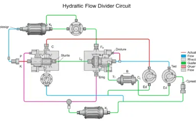
Principle Diagram of a Hydrostatic Transmission
| Parameter | Symbol | Value | Unit |
|---|---|---|---|
| Pump Displacement | \(V_p\) | 3.05 | in³/rev |
| Pump Speed | \(N_p\) | 1500 | rpm |
| Pump Volumetric Efficiency | \(\eta_{v,p}\) | 0.95 | - |
| Pump Hydromechanical Efficiency | \(\eta_{hm,p}\) | 0.90 | - |
| Motor Displacement | \(V_m\) | 2.44 | in³/rev |
| Motor Volumetric Efficiency | \(\eta_{v,m}\) | 0.94 | - |
| Motor Hydromechanical Efficiency | \(\eta_{hm,m}\) | 0.88 | - |
Questions to Solve
- Calculate the overall efficiency of the pump (\(\eta_{g,p}\)).
- Calculate the theoretical flow rate (\(Q_{th,p}\)) and the actual flow rate (\(Q_{r,p}\)) supplied by the pump.
- Determine the actual rotational speed of the motor (\(N_m\)).
- Calculate the theoretical torque (\(C_{th,m}\)) and the actual torque (\(C_{r,m}\)) supplied by the motor.
- Calculate the overall efficiency of the motor (\(\eta_{g,m}\)) and the total overall efficiency of the transmission (\(\eta_{g,t}\)).
Fundamentals of Hydrostatic Efficiencies
A hydrostatic machine (pump or motor) is never perfect. It experiences two main types of losses, which we quantify with two efficiencies: volumetric efficiency (flow losses, leakage) and hydromechanical efficiency (pressure/torque losses, friction).
1. Volumetric Efficiency (\(\eta_v\))
This measures losses from internal leakage (from the high-pressure side to the low-pressure side). A theoretical flow rate (\(Q_{th}\)) is calculated, but the actual flow rate (\(Q_r\)) is always lower (for a pump) or the required flow rate is higher (for a motor).
\[ \eta_v = \frac{Q_r}{Q_{th}} \text{ (for a pump)} \quad | \quad \eta_v = \frac{Q_{th}}{Q_r} \text{ (for a motor)} \]
2. Hydromechanical Efficiency (\(\eta_{hm}\))
This measures losses from friction (fluid and mechanical). A theoretical torque (\(C_{th}\)) is needed to overcome pressure, but the actual input torque (\(C_r\)) required is higher (for a pump) or the output torque is lower (for a motor).
\[ \eta_{hm} = \frac{C_{th}}{C_r} \text{ (for a pump)} \quad | \quad \eta_{hm} = \frac{C_r}{C_{th}} \text{ (for a motor)} \]
Solution: Overall Efficiency of a Hydrostatic Transmission
Question 1: Calculate the overall efficiency of the pump (\(\eta_{g,p}\)).
Principle
The overall efficiency (\(\eta_g\)) of a hydraulic component is simply the product of its two "internal" efficiencies: volumetric efficiency (\(\eta_v\)) and hydromechanical efficiency (\(\eta_{hm}\)). It represents the total energy efficiency of the component.
Mini-Lesson
Overall efficiency quantifies the portion of input power that is effectively converted into useful output power. For a pump, it is the ratio of hydraulic power delivered to the mechanical power consumed. \(\eta_g = \eta_v \times \eta_{hm}\) is a fundamental relationship.
Educational Note
Think of efficiencies as successive "filters." The input power passes through a first filter (friction, \(\eta_{hm}\)) and then a second (leakage, \(\eta_v\)). The overall efficiency is what remains at the end.
Standards
These efficiency calculations are standardized (e.g., by ISO or NFPA) to allow for the comparison of components.
Formula(s)
The formula to apply is the definition of overall efficiency:
Assumptions
We assume the given efficiencies are constant for the studied operating point (speed and pressure).
- Losses in the lines between the pump and motor are neglected.
Given Data
We extract the pump data from the problem statement:
| Parameter | Symbol | Value | Unit |
|---|---|---|---|
| Pump Volumetric Efficiency | \(\eta_{v,p}\) | 0.95 | - |
| Pump Hydromechanical Efficiency | \(\eta_{hm,p}\) | 0.90 | - |
Tips
An efficiency is always a number between 0 and 1 (or 0% and 100%). If your calculation yields a result greater than 1, there is an error (often an inversion in a division).
Diagram (Before Calculation)
This diagram illustrates the concept of efficiency: mechanical power enters the pump, and hydraulic power (useful) and losses (heat) exit.
Power Balance (Pump)
Calculation(s)
The calculation consists of applying the overall efficiency formula using the values provided in the "Given Data" table for the pump.
Step 1: State the formula
This is the base formula defining overall efficiency as the product of the two sub-efficiencies.
Step 2: Substitute the values
We replace \(\eta_{v,p}\) with its value (0.95) and \(\eta_{hm,p}\) with its value (0.90) from the data table.
The numerical application 0.95 multiplied by 0.90 gives 0.855. This is the pump's overall efficiency.
Diagram (After Calculation)
The previous diagram updated with efficiency values. For 100% of mechanical power input, we get 85.5% of useful hydraulic power output.
Pump Overall Efficiency
Analysis
An overall efficiency of 85.5% is a typical magnitude for a piston pump at this operating range. This means that 14.5% of the input power is lost, primarily as heat (due to leakage and friction).
Common Pitfalls
Do not add efficiencies! Losses multiply (or rather, efficiencies multiply). Adding 0.95 and 0.90 makes no physical sense.
Key Takeaways
- Overall efficiency is the product of volumetric and hydromechanical efficiency.
- \(\eta_g = \eta_v \times \eta_{hm}\)
Did You Know?
Efficiencies are not constant! They vary significantly with rotational speed, operating pressure, and fluid viscosity (temperature). Manufacturer catalogs provide "efficiency curves" (isoplot charts) to show this.
FAQ
Frequently asked questions for this step.
Final Result
Your Turn
If another pump has an \(\eta_{v,p} = 0.98\) and an \(\eta_{hm,p} = 0.92\), what is its overall efficiency \(\eta_{g,p}\)? (Round to 4 decimal places)
Summary Card
Question 1 Summary:
- Key Concept: Energy efficiency of a component.
- Essential Formula: \(\eta_g = \eta_v \times \eta_{hm}\).
- Result: \(0.95 \times 0.90 = 0.855\).
Question 2: Calculate the theoretical flow rate (\(Q_{th,p}\)) and the actual flow rate (\(Q_{r,p}\)) supplied by the pump.
Principle
The theoretical flow rate (\(Q_{th}\)) is the volume the pump *should* deliver if it were perfect, based solely on its geometry (displacement) and its speed. The actual flow rate (\(Q_r\)) is what it *actually* delivers, taking into account internal leakage (quantified by \(\eta_v\)).
Mini-Lesson
The displacement (\(V_p\)), in in³/rev, is the volume of fluid displaced by the pump per revolution. By multiplying it by the rotational speed (\(N_p\)), in rpm, we get a volume per minute: the theoretical flow rate. The actual flow rate is this theoretical flow rate minus the leakage losses.
Educational Note
This is the first step in understanding what actually goes to the motor. The motor will not receive the theoretical flow, but the pump's actual flow.
Standards
The standard unit for flow rate in US fluid power is US Gallons Per Minute (gpm). There are 231 cubic inches in 1 US gallon.
Formula(s)
Theoretical Flow Rate (US Formula)
(With \(V_p\) in in³/rev, \(N_p\) in rpm, and \(Q_{th,p}\) in gpm)
Actual Flow Rate (Pump)
Assumptions
We continue to assume the efficiencies are constant at the given operating point.
Given Data
We need the pump's data:
| Parameter | Symbol | Value | Unit |
|---|---|---|---|
| Pump Displacement | \(V_p\) | 3.05 | in³/rev |
| Pump Speed | \(N_p\) | 1500 | rpm |
| Pump Volumetric Efficiency | \(\eta_{v,p}\) | 0.95 | - |
Tips
The most important point here is unit management! The "231" in the formula is the conversion factor from cubic inches to gallons. \(1 \text{ US Gallon} = 231 \text{ in}^3\). \(V_p \times N_p\) gives in³/min, so we divide by 231 to get gal/min (gpm).
Diagram (Before Calculation)
This diagram illustrates the difference between theoretical flow (generated by geometry) and actual flow (what exits, after leakage).
Pump Flow Rates
Calculation(s)
We will first calculate the theoretical (perfect) flow rate before applying the volumetric efficiency to find the actual flow rate.
Step 1: Calculate theoretical flow rate (\(Q_{th,p}\))
We apply the formula \(Q_{th,p} = (V_p \times N_p) / 231\). We use the displacement \(V_p = 3.05 \text{ in³/rev}\) and speed \(N_p = 1500 \text{ rpm}\) from the given data.
The result is in gallons per minute (gpm).
Step 2: Calculate actual flow rate (\(Q_{r,p}\))
We apply the volumetric efficiency formula for a pump: \(Q_{r,p} = Q_{th,p} \times \eta_{v,p}\). We use the theoretical flow (19.805 gpm) calculated in Step 1 and the efficiency \(\eta_{v,p} = 0.95\) from the data.
This is the flow that will actually exit the pump to supply the motor. The missing 0.99 gpm (19.805 - 18.815) is the internal leakage.
Diagram (After Calculation)
The conceptual diagram updated with the calculated values. The theoretical flow of 19.8 gpm is reduced by leakage (0.99 gpm) to give an actual flow of 18.8 gpm.
Pump Flow Rates (Calculated)
Analysis
The difference, \(Q_{th,p} - Q_{r,p} \approx 0.99 \text{ gpm}\), is the leakage flow rate. This isn't oil "leaving" the system; it's oil that returns from the high-pressure side to the low-pressure side *inside* the pump, without doing useful work.
Common Pitfalls
Forgetting the conversion factor 231 is the #1 error. Always write units in your calculations and check their consistency. \( \text{in³/min} \rightarrow \text{gpm}\) is a critical conversion.
Key Takeaways
- \(Q_{th} = (V \times N) / 231\)
- \(Q_r = Q_{th} \times \eta_v\) (for a pump)
- \(1 \text{ US Gallon} = 231 \text{ in}^3\)
Did You Know?
This internal leakage flow generates a lot of heat. It's the result of a small flow of oil (0.99 gpm) being forced across a large pressure drop (2900 psi). This is one of the main sources of heat in a hydraulic circuit.
FAQ
Frequently asked questions for this step.
Final Result
Your Turn
If a pump has \(V_p = 3.66 \text{ in³/rev}\) and runs at \(1000 \text{ rpm}\) with \(\eta_{v,p} = 0.9\), what is its actual flow rate \(Q_{r,p}\) in gpm? (Round to 2 decimals)
Summary Card
Question 2 Summary:
- Key Concept: Theoretical vs. Actual Flow.
- Formulas: \(Q_{th} = (V \times N) / 231\), \(Q_r = Q_{th} \times \eta_v\).
- Calculation: \(Q_{th} = (3.05 \times 1500) / 231 = 19.81\). \(Q_r = 19.81 \times 0.95 = 18.82\).
Question 3: Determine the actual rotational speed of the motor (\(N_m\)).
Principle
The actual flow rate exiting the pump (\(Q_{r,p}\)) is the actual flow rate entering the motor (\(Q_{r,m}\)). This flow must be sufficient to "fill" the motor's displacement each revolution (\(Q_{th,m}\)) *and* compensate for the motor's internal leakage (\(\eta_{v,m}\)). We must work backward from the actual flow to the motor's theoretical flow, and then to its speed.
Mini-Lesson
For a motor, the volumetric efficiency relationship is inverted: \(\eta_{v,m} = \frac{Q_{th,m}}{Q_{r,m}}\) because the actual flow (\(Q_{r,m}\)) must be *greater* than the theoretical flow (\(Q_{th,m}\)) to compensate for leakage while still providing rotation. Once \(Q_{th,m}\) is found, we use \(Q_{th,m} = (V_m \times N_m) / 231\) to find \(N_m\).
Educational Note
This is the key to the transmission. Flow determines speed. The pump sends a flow of 18.82 gpm. This flow "forces" the motor to turn. The output speed is not a choice; it's a consequence of the input flow and the motor's geometry.
Standards
The principle of flow conservation (what leaves the pump enters the motor, minus line losses) is fundamental.
Formula(s)
Flow Conservation
Theoretical Flow (Motor)
Speed (Motor)
Assumptions
We neglect pressure drop and leakage in the hoses between the pump and motor. We therefore assume \(Q_{r,m} = Q_{r,p}\).
Given Data
We use the result from Q2 and the motor data:
| Parameter | Symbol | Value | Unit |
|---|---|---|---|
| Actual Flow (from Q2) | \(Q_{r,p}\) | 18.815 | gpm |
| Motor Displacement | \(V_m\) | 2.44 | in³/rev |
| Motor Volumetric Efficiency | \(\eta_{v,m}\) | 0.94 | - |
Tips
The classic error is to invert the formula for the motor. Remember: the *incoming* flow (Actual, \(Q_r\)) is *larger* than the *turning* flow (Theoretical, \(Q_{th}\)). So \(\eta_v = Q_{th} / Q_r\). To find the useful part (\(Q_{th}\)), we correctly multiply \(Q_r \times \eta_v\).
Diagram (Before Calculation)
This diagram shows the actual flow (\(Q_r\)) entering the motor, which splits into a leakage flow and a theoretical flow (\(Q_{th}\)) that generates the rotation (\(N_m\)).
Motor Flow Rates
Calculation(s)
Step 1: Flow entering the motor
We assume all actual flow from the pump enters the motor (neglecting line losses). We use the result from Question 2.
This actual flow of 18.815 gpm is what enters the motor.
Step 2: Theoretical (useful) flow of the motor
For a motor, the actual flow \(Q_{r,m}\) splits in two: a part that leaks (\(1 - \eta_{v,m}\)) and a part that creates rotation (the theoretical flow \(Q_{th,m}\)). Thus, \(Q_{th,m} = Q_{r,m} \times \eta_{v,m}\). We use \(Q_{r,m}\) from Step 1 and \(\eta_{v,m} = 0.94\) from the data.
This means that of the 18.815 gpm that enter, only 17.686 gpm are used to turn the motor. The rest (1.129 gpm) is internal leakage.
Step 3: Calculate the motor's actual speed
We isolate \(N_m\) from the formula \(Q_{th,m} = (V_m \times N_m) / 231\), which gives \(N_m = (Q_{th,m} \times 231) / V_m\). We use \(Q_{th,m}\) from Step 2 and \(V_m = 2.44 \text{ in³/rev}\) from the data. The units (gpm \(\times\) in³/gal) / (in³/rev) will correctly give rev/min (rpm).
The final rotational speed of the motor is therefore approximately 1674.4 rpm.
Diagram (After Calculation)
The conceptual diagram updated with the calculated values, showing the transformation of flow into speed.
Motor Speed (Calculated)
Analysis
The pump runs at 1500 rpm and the motor at 1674 rpm. The motor runs *faster* than the pump. This is normal: its displacement (2.44 in³/rev) is smaller than the pump's (3.05 in³/rev). It acts as a torque "reducer" and speed "multiplier".
Common Pitfalls
The classic error is to mix up the motor's volumetric efficiency formula. Remember: the *actual* flow (what goes in) is always *greater* than the *theoretical* flow (what does the turning) for a motor. \(Q_r > Q_{th}\). Therefore, \(\eta_v = Q_{th} / Q_r\).
Key Takeaways
- The pump's actual flow is the motor's actual flow (\(Q_{r,p} = Q_{r,m}\)).
- For a motor: \(\eta_{v,m} = \frac{Q_{th,m}}{Q_{r,m}}\)
- Speed is calculated from *theoretical* flow: \(N_m = (Q_{th,m} \times 231) / V_m\).
FAQ
Frequently asked questions for this step.
Final Result
Your Turn
If a motor receives \(Q_{r,m} = 15.85 \text{ gpm}\), has \(\eta_{v,m} = 0.9\) and \(V_m = 3.05 \text{ in³/rev}\), what is its speed \(N_m\) in rpm? (Round to nearest whole number)
Summary Card
Question 3 Summary:
- Key Concept: Flow rate determines speed.
- Formulas: \(Q_{th,m} = Q_{r,m} \times \eta_{v,m}\), \(N_m = (Q_{th,m} \times 231) / V_m\).
- Calculation: \(Q_{th,m} = 18.815 \times 0.94 = 17.686\). \(N_m = (17.686 \times 231) / 2.44 = 1674.4\).
Question 4: Calculate the theoretical torque (\(C_{th,m}\)) and the actual torque (\(C_{r,m}\)) supplied by the motor.
Principle
The pressure (\(\Delta p\)) acting on the displacement (\(V_m\)) generates a theoretical torque (\(C_{th,m}\)). This is the torque that *should* be produced if the motor were perfect. The actual torque (\(C_{r,m}\)) is what is *actually* available at the output, after frictional losses (quantified by \(\eta_{hm,m}\)).
Mini-Lesson
Pressure creates a force, and this force acting on the motor's pistons/vanes creates torque. Theoretical torque is the direct conversion of pressure energy into rotational torque. Actual torque is this theoretical torque minus frictional losses.
Educational Note
Just as flow determines speed, pressure determines torque. The 2900 psi pressure is "pushed" by the pump. This pressure "forces" the motor to develop torque.
Standards
In US engineering, torque is typically in pound-inches (lb-in) or pound-feet (lb-ft).
Formula(s)
Theoretical Torque (US Formula)
(With \(V_m\) in in³/rev, \(\Delta p\) in psi, and \(C_{th,m}\) in lb-in)
Actual Torque (Motor)
Assumptions
We assume the pressure \(\Delta p = 2900 \text{ psi}\) is constant and fully applied to the motor (no line losses).
Given Data
We need the motor data and the pressure:
| Parameter | Symbol | Value | Unit |
|---|---|---|---|
| Pressure | \(\Delta p\) | 2900 | psi |
| Motor Displacement | \(V_m\) | 2.44 | in³/rev |
| Motor Hydromechanical Efficiency | \(\eta_{hm,m}\) | 0.88 | - |
Tips
The formula \(C_{th} = (V \times \Delta p) / (2\pi)\) is fundamental. It comes from \(C = P_h / N\), where \(P_h = \Delta p \times Q\) and \(Q = V \times N\). \(C_{th} = (\Delta p \times V \times N) / N = \Delta p \times V\). This gives torque *per radian* (lb-in/rad). To get torque *per revolution*, we must divide by \(2\pi\) rad/rev.
Diagram (Before Calculation)
This diagram shows the pressure (\(\Delta p\)) entering the motor, which generates a theoretical torque (\(C_{th}\)). This torque is reduced by frictional losses to give the actual torque (\(C_r\)) at the output.
Motor Torques
Calculation(s)
Step 1: Calculate theoretical torque (\(C_{th,m}\))
We use the US customary formula. We use \(V_m = 2.44 \text{ in³/rev}\) and \(\Delta p = 2900 \text{ psi}\) from the given data.
The theoretical (perfect) torque the motor should produce is 1126.19 lb-in.
Step 2: Calculate actual torque (\(C_{r,m}\))
The actual output torque is the theoretical torque (generated by pressure) minus frictional losses, which are quantified by \(\eta_{hm,m}\). We apply \(C_{r,m} = C_{th,m} \times \eta_{hm,m}\). We use \(C_{th,m}\) from Step 1 and \(\eta_{hm,m} = 0.88\) from the data.
This is the useful torque, actually available on the motor's output shaft to drive the load (e.g., the wheel).
Diagram (After Calculation)
The conceptual diagram updated with calculated values. The pressure generates 1126.2 lb-in of theoretical torque, but 135.1 lb-in is lost to friction, leaving only 991.1 lb-in at the output.
Motor Torques (Calculated)
Analysis
The motor develops a theoretical torque of 1126.2 lb-in, but due to internal friction (mechanical and fluid), the actual torque available on the output shaft is only 991.1 lb-in. The difference, 135.1 lb-in, is "lost" to overcome this friction.
Common Pitfalls
For a motor, the *actual* torque is *smaller* than the *theoretical* torque. This is the reverse of a pump, where the actual input torque must be greater than theoretical to compensate for friction.
Key Takeaways
- Pressure generates torque.
- \(C_{th} = (V \times \Delta p) / (2\pi)\) (with units psi, in³/rev, lb-in)
- \(C_r = C_{th} \times \eta_{hm}\) (for a motor)
FAQ
Frequently asked questions for this step.
Final Result
Your Turn
If a motor has \(V_m = 3.05 \text{ in³/rev}\) under \(\Delta p = 2175 \text{ psi}\) with \(\eta_{hm,m} = 0.9\), what is its actual torque \(C_{r,m}\) in lb-in? (Round to 1 decimal)
Summary Card
Question 4 Summary:
- Key Concept: Pressure generates torque.
- Formulas: \(C_{th} = (V \times \Delta p) / (2\pi)\), \(C_r = C_{th} \times \eta_{hm}\).
- Calculation: \(C_{th} = (2.44 \times 2900) / (2\pi) = 1126.2\). \(C_r = 1126.2 \times 0.88 = 991.1\).
Question 5: Calculate the overall efficiency of the motor (\(\eta_{g,m}\)) AND the total overall efficiency of the transmission (\(\eta_{g,t}\)).
Principle
Final step! The motor's overall efficiency is calculated just like the pump's (product of efficiencies). The *total* overall efficiency of the transmission is the product of the pump's overall efficiency AND the motor's overall efficiency. The losses stack up.
Mini-Lesson
Mechanical power (\(P_{in}\)) enters the pump. The pump converts it with its efficiency (\(\eta_{g,p}\)). The resulting hydraulic power (\(P_{hyd}\)) travels to the motor. The motor converts it with its efficiency (\(\eta_{g,m}\)). The final mechanical power (\(P_{out}\)) is therefore \(P_{out} = P_{in} \times \eta_{g,p} \times \eta_{g,m}\). The total efficiency is \(\eta_{g,t} = P_{out} / P_{in} = \eta_{g,p} \times \eta_{g,m}\).
Educational Note
It's often a surprise to see how much the efficiencies drop. Two "efficient" components (e.g., 90% and 90%) do not result in a 90% or even 81% (\(0.9 \times 0.9\)) transmission. Here, our components are 85.5% and (as we'll see) 82.7%. The total will be much lower.
Standards
The definition of an energy chain's efficiency is the product of the efficiencies of each link in the chain.
Formula(s)
Overall Efficiency (Motor)
Overall Efficiency (Transmission)
Assumptions
We use the given efficiency values, assumed constant.
Given Data
We gather all our efficiencies:
| Parameter | Symbol | Value | Unit |
|---|---|---|---|
| Motor Volumetric Efficiency | \(\eta_{v,m}\) | 0.94 | - |
| Motor Hydromechanical Efficiency | \(\eta_{hm,m}\) | 0.88 | - |
| Pump Overall Efficiency (from Q1) | \(\eta_{g,p}\) | 0.855 | - |
Tips
To calculate the final output power (in hp), the formula is \(P_{out} = (C_{r,m} \times N_m) / 63025\). With our results: \(P_{out} = (991.05 \times 1674.37) / 63025 \approx 26.3 \text{ hp}\). We can check the input power: \(C_{th,p} = (3.05 \times 2900) / (2\pi) = 1409.5\). \(C_{r,p} = C_{th,p} / \eta_{hm,p} = 1409.5 / 0.9 = 1566.1\). \(P_{in} = (1566.1 \times 1500) / 63025 \approx 37.27 \text{ hp}\). The total efficiency is \(26.3 / 37.27 \approx 0.7056\). Let's check against our \(\eta_{g,t}\) calculation...
Diagram (Before Calculation)
This diagram shows the complete power chain. Input power (\(P_{in}\)) is reduced once by the pump's efficiency (\(\eta_{g,p}\)), and the resulting hydraulic power (\(P_{hyd}\)) is reduced a second time by the motor's efficiency (\(\eta_{g,m}\)) to give the final output power (\(P_{out}\)).
Power Chain and Efficiencies
Calculation(s)
Step 1: Calculate the motor's overall efficiency (\(\eta_{g,m}\))
Just as with the pump (Q1), the motor's overall efficiency is the product of its volumetric (\(\eta_{v,m} = 0.94\)) and hydromechanical (\(\eta_{hm,m} = 0.88\)) efficiencies.
The motor's overall efficiency is therefore 82.72%.
Step 2: Calculate the total overall efficiency (\(\eta_{g,t}\))
The efficiency of the complete transmission is the product of the efficiencies of each link. We multiply the pump's overall efficiency (\(\eta_{g,p} = 0.855\), from Q1) by the motor's overall efficiency (\(\eta_{g,m} = 0.8272\), from Step 1 above).
The final efficiency of the transmission is approximately 70.73%. This means that for every 100 hp of mechanical power supplied to the pump, only 70.73 hp is recovered on the motor shaft.
Diagram (After Calculation)
This Sankey diagram illustrates the cascade of losses. 100% of the power enters; 14.5% is lost in the pump. 85.5% remains (as hydraulic power). Of this 85.5%, we lose 17.28% (which is \(1 - 0.8272\)) in the motor, corresponding to \(0.855 \times (1 - 0.8272) \approx 14.8\%\) of the total. The final output is 70.7%.
Sankey Diagram (Power Flow)
Analysis
The motor's overall efficiency is 82.7%. The total overall efficiency of the transmission is 70.7%.
Our power check (in "Tips") gave 0.7056. The small difference is due to sequential rounding. Both methods are consistent.
Common Pitfalls
Never average the efficiencies! (\(0.855 + 0.8272) / 2 = 0.8411\), which is completely wrong and far too optimistic. Efficiencies in a chain always multiply.
Key Takeaways
- The total overall efficiency is the product of the overall efficiencies of each component in the chain.
- \(\eta_{g,t} = \eta_{g,p} \times \eta_{g,m} \times ...\)
Did You Know?
For a hydrostatic transmission, 70.7% efficiency is acceptable, but perhaps a bit low. A mechanical transmission (gears or driveshaft) easily reaches 95-98% efficiency. The "price" paid for the flexibility of hydraulics (continuous variation, high torque at low speed) is a greater energy loss.
Final Result
Your Turn
If a pump's overall efficiency is \(\eta_{g,p} = 0.9\) and the motor's is \(\eta_{g,m} = 0.8\), what is the total efficiency \(\eta_{g,t}\) (as a decimal)?
Summary Card
Question 5 Summary:
- Key Concept: Efficiencies in a chain are multiplied.
- Formulas: \(\eta_{g,m} = \eta_{v,m} \times \eta_{hm,m}\), \(\eta_{g,t} = \eta_{g,p} \times \eta_{g,m}\).
- Calculation: \(\eta_{g,m} = 0.94 \times 0.88 = 0.8272\). \(\eta_{g,t} = 0.855 \times 0.8272 = 0.7073\).
Interactive Tool: Hydraulic Power Simulator
Explore the relationship between flow, pressure, and power. This simulator calculates the theoretical hydraulic power (energy carried by the fluid) and the actual mechanical power required at the input (assuming a fixed 85% overall efficiency).
Input Parameters
Key Results
Final Quiz: Test Your Knowledge
1. What is the overall efficiency (\(\eta_g\)) of a component?
2. Volumetric efficiency (\(\eta_v\)) quantifies losses from...
3. A pump has a theoretical flow \(Q_{th} = 100 \text{ gpm}\) and an \(\eta_v = 0.9\). What is its actual flow \(Q_r\)?
4. Which of these statements is true for a complete transmission (pump + motor)?
5. If \(\eta_{g,p} = 0.9\) and \(\eta_{g,m} = 0.8\), the total efficiency \(\eta_{g,t}\) is...
Glossary
- Volumetric Efficiency (\(\eta_v\))
- The ratio of theoretical to actual flow rate. It quantifies flow losses due to internal leakage in the component.
- Hydromechanical Efficiency (\(\eta_{hm}\))
- The ratio of theoretical to actual torque (or pressure). It quantifies torque losses due to friction (mechanical and viscous).
- Overall Efficiency (\(\eta_g\))
- The product of volumetric and hydromechanical efficiency (\(\eta_v \times \eta_{hm}\)). It represents the total energy efficiency of the component.
- Displacement (V)
- The volume of fluid displaced or admitted by a component (pump or motor) for one full revolution. Usually in in³/rev.
- Hydrostatic Transmission
- A functional assembly composed of a pump and one or more hydraulic motors, which transmits mechanical power via a pressurized fluid.

0 Comments