Interpreting a Log Splitter Hydraulic Schematic
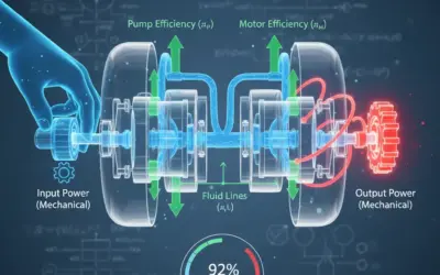
Context: Hydraulic PowerTechnology using pressurized fluids (oil) to transmit power and control motion. Also known as Fluid Power..
Log splitters use hydraulic power to generate enormous splitting forces. Understanding their schematic is essential for any maintenance technician or designer. This exercise invites you to analyze a typical log splitter's hydraulic circuit to understand its different operating cycles.
Educational Note: This exercise will teach you to identify standard hydraulic components (pump, cylinder, valve, pressure relief valve) and trace the flow of oil to understand the machine's work cycles (extend, retract, neutral).
Learning Objectives
- Identify standard symbols (ISO 1219 / ANSI) for main circuit components.
- Analyze the 'splitting' cycle (cylinder extension).
- Analyze the 'return' cycle (cylinder retraction).
- Understand the role of a pressure relief valve in protecting the circuit.
- Analyze the neutral position of an "open center" circuit.
Study Data
Technical Specifications
| Characteristic | Value |
|---|---|
| Circuit Type | Open Center (Tandem) |
| Actuator | Double-acting Cylinder |
| Primary Safety | Direct-acting Pressure Relief Valve |
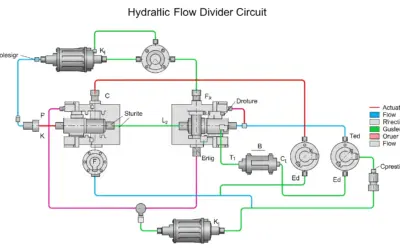
Log Splitter Hydraulic Schematic
| Parameter Name | Symbol | Value | Unit |
|---|---|---|---|
| Relief Valve Setting (Max Pressure) | \(P_{max}\) | 2500 | PSI |
| Pump Flow Rate | \(Q_p\) | 3 | GPM |
| Cylinder Piston Diameter (Bore) | \(D\) | 3.0 | in |
Questions to Solve
- Identify Components: List the components numbered 1 through 5 on the schematic.
- Analyze "Neutral" Position (Lever Centered): What happens when the lever is in the center? Where does the oil go, and why is this an "economical" setup?
- Analyze "Splitting" Position (Lever Pushed): Describe the oil's path. What is the role of component (3) during this phase?
- Analyze "Return" Position (Lever Pulled): Describe the oil's path to retract the cylinder rod.
- Calculation (Bonus): Calculate the maximum splitting force (in pounds-force) the cylinder can develop, using the data from the table. (Hint: \(F = P \times S\) and \(S = \pi \times (D/2)^2\)).
Fundamentals of Hydraulic Power
To read this schematic, you need to know the basic symbols and operating principle of a hydraulic circuit. The oil (an incompressible fluid) is set in motion by the pump, creating flow. Resistance to this flow creates pressure.
1. Key Components
- Pump (1): Creates flow (oil movement, in GPM). It does not create pressure; resistance to its flow generates pressure.
- Cylinder (5): An actuator. Converts hydraulic energy (pressure, flow) into mechanical energy (force, speed).
- Directional Control Valve (DCV) (4): The "switch". It directs oil to the cylinder (port A or B) or sends it back to the tank (port T).
- Pressure Relief Valve (PRV) (3): The "safety valve". Protects the circuit from overpressure. It remains closed as long as the pressure is below its set (rated) value.
- Reservoir (Tank) (2): Stores the oil, allows it to cool, and lets contaminants settle.
2. Reading Schematics (Symbols)
Hydraulic schematics use standard symbols (ISO 1219 / ANSI). Arrows indicate flow direction. 'T' shapes indicate a blocked line. The boxes in a DCV represent its different positions (here, 3 positions). You always analyze the active position (the box that lines up with the ports).
Solution: Interpreting a Log Splitter Hydraulic Schematic
Question 1: Identify Components
Principle
The objective is to match each number on the schematic to its corresponding standard hydraulic component.
Mini-Lesson
Standardization (e.g., ISO 1219, ANSI) is essential in engineering. It allows an American engineer to understand a schematic drawn by a German or Japanese colleague. Each symbol uniquely represents a function (pump, motor, valve) unambiguously.
Solution (replaces Calculations)
By observing the schematic and the standard symbols, we can identify:
- (1) Hydraulic Pump: Circle symbol with a black triangle pointing outward (indicating flow out). It is driven by a motor (M).
- (2) Reservoir (Tank): Symbol for a vented tank.
- (3) Pressure Relief Valve (PRV): Mounted in parallel ("Tee'd off"). Stays closed (blocked arrow) and opens against a spring (zigzag symbol) if the pressure (dashed pilot line) exceeds the setting.
- (4) 4/3 Directional Control Valve (DCV): A valve with 3 boxes (3 positions) and 4 ports (P, T, A, B).
- (5) Double-Acting Cylinder: A piston that can be moved by fluid pressure in both directions.
Final Answer
Your Turn
If the pump flows at 3 GPM (Gallons Per Minute), how many gallons does it flow in 30 seconds (0.5 minutes)?
Memo Card
Q1 Summary:
- Key Concept: Recognition of basic hydraulic symbols (Pump, Cylinder, DCV, PRV, Tank).
Question 2: Analyze "Neutral" Position
Principle
Analyzing the "Neutral" position means tracing the path of the oil when the DCV (4) is in its center position (spring-centered).
Mini-Lesson
An "Open Center" valve (like this "tandem center") is designed for fixed-displacement pumps (like gear pumps). In neutral, the pump doesn't have to "work" because the oil flows back to the tank with no resistance. This prevents overheating and saves energy. "Closed Center" valves are used with variable-displacement pumps.
Reasoning (replaces Calculations)
In neutral, we analyze the center square of the DCV (4):
- Oil from the pump (1) arrives at port P.
- In the center square, an arrow connects P directly to T (Tank/Reservoir).
- Ports A and B (to the cylinder) are blocked (T-symbols).
The oil drawn from the reservoir (2) by the pump (1) flows through the DCV from P to T and returns directly to the reservoir (2).
Key Takeaway
This is an "open center" (or tandem center) setup. The oil circulates freely at low pressure back to the tank when not in use. This is "economical" because the pump isn't working against pressure, which saves energy from the motor (M) and prevents the oil from overheating.
Final Answer
Your Turn
In neutral (open center), is the circuit pressure (1) maximum or (2) very low?
Memo Card
Q2 Summary:
- Key Concept: Open Center (Tandem).
- Flow Path: P → T.
- Advantage: Energy saving, low heat.
Question 3: Analyze "Splitting" Position
Principle
Analyze the "Splitting" (rod extension) cycle by tracing the oil flow when the lever is shifted to one side (e.g., the left square).
Mini-Lesson
The Pressure Relief Valve (PRV) (3) is the most important safety component. It is always mounted in parallel just after the pump. It compares the circuit pressure (via the pilot line, a dashed line) to the force of a pre-set spring. If the pressure exceeds the setting, it opens and dumps the pump's flow (P) to the tank (T), preventing pressure from rising any further.
Reasoning (replaces Calculations)
The operator shifts the lever, aligning one of the outer squares:
- Oil from the pump (P) is now directed to port A (path P → A).
- Port A feeds the "cap end" (piston side) of the cylinder (5). Pressure builds on the full piston area, pushing the rod out to split the log.
- Oil pushed out of the "rod end" exits through port B, flows through the DCV (path B → T), and returns to the tank.
Role of the PRV (3)
During this phase, the oil can no longer flow freely to the tank. Pressure rises based on the log's resistance. If the log is too tough, the pressure will increase until it hits the set pressure (e.g., 2500 PSI) of the PRV (3). At that moment, the PRV opens and diverts the pump's flow directly to the tank, protecting the pump, hoses, and cylinder from dangerous overpressure.
Final Answer
Your Turn
If the PRV fails (stuck closed) and the log is "un-splittable," what will happen? (1) The engine will stall or a component will break, (2) The cylinder will retract.
Memo Card
Q3 Summary:
- Key Concept: Work cycle (extend) and safety.
- Flow Path: P → A and B → T.
- Safety: The PRV (3) dumps P → T in case of overpressure.
Question 4: Analyze "Return" Position
Principle
Analyze the "Return" (rod retraction) cycle by tracing the oil flow when the lever is shifted to the other side (e.g., the right square).
Mini-Lesson
In a double-acting cylinder, the "cap end" (piston) area is larger than the "rod end" area. This rod-end area is called the "annular area" (piston area minus rod area). For the same flow (GPM) and pressure (PSI), the cylinder will retract faster (V=Q/S) but with less force (F=PxS) than it extends.
Reasoning (replaces Calculations)
The operator shifts the lever the other way:
- Oil from the pump (P) is now directed to port B (path P → B).
- Port B feeds the "rod end" (annular area) of the cylinder (5). Pressure builds on this smaller area, pushing the cylinder to retract the rod.
- Oil pushed out of the "cap end" exits through port A, flows through the DCV (path A → T), and returns to the tank.
Tip
The return force is weaker than the splitting force (because the rod-end area is smaller), but the return speed is often faster (for the same flow, there is a smaller volume to fill). This is a design trade-off.
Final Answer
Your Turn
For the same pressure, is the return force (1) greater than or (2) less than the splitting force?
Memo Card
Q4 Summary:
- Key Concept: Work cycle (retract).
- Flow Path: P → B and A → T.
Question 5: Calculate Splitting Force
Principle
The maximum force is achieved when the pressure reaches the circuit's maximum, which is the setting of the pressure relief valve (3). The force is the product of this pressure and the area it acts upon (the piston area).
Mini-Lesson
The fundamental relationship \(F = P \times S\) (Force = Pressure × Area) is the heart of hydraulic power. Pressure (P) is a force per unit area (e.g., Pounds per Square Inch, or PSI). By multiplying it by the area (S) it acts on (here, the piston), we get the total force (F) in pounds.
Educational Note
For this calculation, the most important force is the "push" force (rod extension), as this is what splits the log. Therefore, we use the full piston area. The "pull" or retraction force would be weaker because the area is reduced by the rod (the annular area).
Standards
Force and pressure calculations in the US use the US Customary system. It is crucial that units are consistent. To get Force in Pounds (lbs), the Pressure must be in Pounds per Square Inch (PSI) and the Area in Square Inches (sq-in).
Formula(s)
Force (F)
Piston Area (S)
Assumptions
For this calculation, we make the following assumptions:
- We neglect internal friction forces in the cylinder (seals, etc.).
- The 2500 PSI pressure is applied evenly across the entire piston face.
- The hydraulic fluid is considered incompressible.
Given Data
We extract the necessary data from the problem statement:
| Parameter | Symbol | Value | Unit |
|---|---|---|---|
| Maximum Pressure (PRV Setting) | P | 2500 | PSI |
| Piston Diameter (Bore) | D | 3.0 | in |
Tip
A quick rule of thumb: "A 3-inch cylinder has about 7 square inches of area." You can do a quick mental check: \(7 \text{ sq-in} \times 2500 \text{ PSI} \approx 17500 \text{ lbs}\). This is a great way to verify your answer is in the right ballpark before doing the exact calculation.
Schematic (Before Calculation)
The calculation focuses on the cylinder (5) during the splitting phase (P → A). The P_max acts on the piston area S.
Force Calculation Principle
Calculation(s)
This is the heart of the solution. We will now apply the formulas with the given data, breaking down each step to follow the logic.
Step 1: Check Units
To use the formula \(F = P \times S\) and get Force in Pounds (lbs), we need Pressure (P) in Pounds per Square Inch (PSI) and Area (S) in Square Inches (sq-in). Our data is already in these units, so no conversion is needed.
Step 2: Calculate Piston Area (S)
The formula for the area of a circle is \(S = \pi \times R^2\). We need the radius (R), which is half the diameter (D).
Now, we can calculate the area (S) in square inches:
Step 3: Calculate Force (F)
We have the Pressure (P) and Area (S) in the correct units. We apply the formula \(F = P \times S\) to find the force in Pounds (lbs).
The result is a force of approximately 17,672 pounds-force.
Schematic (After Calculation)
This calculation doesn't produce a new diagram, but the numerical result is the maximum force the splitter can exert.
Reflections
A force of 17,672 lbs is equivalent to approximately 8.8 US Tons (since 1 US Ton = 2000 lbs). This is the immense force that allows the machine to split wood. This force is ONLY achieved if the log provides enough resistance to make the pressure climb all the way to the PRV setting.
Points of Vigilance
Watch your units! The most common error is mixing unit systems. In the US system, for \(F = P \times S\), if P is in PSI (lbs/in²), then S *must* be in in² (square inches) to get F in lbs (pounds).
Key Takeaways
If you remember only two things from this question:
- The fundamental hydraulic force formula: \(F = P \times S\).
- The maximum force of a circuit is determined by the maximum pressure (PRV setting) and the application area (piston area).
Did You Know?
Blaise Pascal, for whom the SI unit of pressure is named, established the core principle of hydraulics: a pressure change at any point in a confined incompressible fluid is transmitted equally throughout the fluid. This is what allows a small pump to generate a huge force at the other end of the circuit.
FAQ
Common questions about this calculation:
Final Answer
Your Turn
What is this maximum force in US Tons? (1 Ton = 2000 lbs). (Round to one decimal place).
Memo Card
Q5 Summary:
- Formula: \(F = P \times S\).
- US Units: Force (lbs), Pressure (PSI), Area (sq-in).
- Key Step: Calculate area from diameter: \(S = \pi \times (D/2)^2\).
Interactive Tool: Force Calculator
Use this tool to see how the pressure setting and cylinder bore affect the maximum splitting force.
Input Parameters
Key Results
Final Quiz: Test Your Knowledge
1. What is the primary role of component (3) (Pressure Relief Valve)?
2. In a 4/3 directional control valve, what does the "4" mean?
3. What does "open center" (or tandem center) mean for the DCV (4)?
4. If you double the pressure (P) and the area (S) does not change, the force (F = P x S)...
5. Which component creates the oil flow?
Glossary
- Fluid Power (Hydraulics)
- Technology that uses a pressurized fluid (usually oil) to transmit energy and control motion.
- Double-Acting Cylinder
- An actuator (linear motor) that can be controlled by hydraulic pressure in both directions (extend and retract).
- 4/3 DCV (Directional Control Valve)
- A "control" component with 4 ports (Pressure, Tank, A, B) and 3 positions (e.g., extend, neutral, retract) to direct the fluid.
- Pressure Relief Valve (PRV)
- A "safety" component. A valve that remains closed and opens at a specific pressure (setting) to divert excess pressure/flow to the tank, protecting the circuit.
- PSI (Pounds per Square Inch)
- The US customary unit of pressure. The force in pounds applied to an area of one square inch.
- GPM (Gallons Per Minute)
- The volume of fluid moved by the pump per unit of time. GPM determines the cylinder's speed.

0 Comments