Hydraulic Hose Pressure Drop (Power Hydraulics)
Context: Understanding Pressure DropThe loss of pressure that occurs as fluid flows through a pipe, hose, or component due to friction. in Power Hydraulics.
In any hydraulic system, from a simple log splitter to a massive excavator, fluid (typically oil) is pushed through hoses to transmit power. As the fluid moves, it rubs against the inner walls of the hose, creating friction. This friction causes a loss of energy, which is observed as a pressure drop (\(\Delta p\)). Calculating this pressure drop is critical for system design. If the drop is too high, the system will be inefficient, generate excessive heat, and may fail to deliver the required force at the actuator (e.g., a hydraulic cylinder).
Pedagogical Note: This exercise will teach you how to apply fundamental fluid dynamics principles (like the Reynolds number and the Darcy-Weisbach equation) to a practical power hydraulics problem. You will learn to calculate fluid velocity, determine the flow regime, and ultimately quantify the pressure lost to friction in a hydraulic hose, a core skill for any hydraulics engineer.
Learning Objectives
- Calculate fluid velocity in a hose using flow rate (GPM) and hose diameter (in).
- Determine the Reynolds NumberA dimensionless quantity used to predict fluid flow patterns. It helps determine if a flow is laminar, turbulent, or transitional. to identify the flow regime.
- Find the friction factor (\(f\)) using the Blasius correlation for turbulent flow.
- Apply the Darcy-WeisbachA key equation in fluid dynamics that relates pressure loss due to friction to the properties of the fluid, flow, and pipe. equation to find the total pressure drop (\(\Delta p\)) in PSI.
Study Data
Technical Data Sheet
| Characteristic | Value |
|---|---|
| Fluid Type | ISO 46 Hydraulic Oil |
| Operating Temperature | 120°F |
| Hose Type | SAE 100R2 Type AT |
| Hose Dash Size | -12 (3/4") |
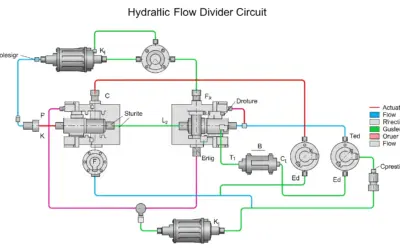
System Schematic
| Parameter | Description or Formula | Value | Unit |
|---|---|---|---|
| Flow Rate | \(Q\) | 20 | GPM |
| Hose Internal Diameter (I.D.) | \(D_{\text{in}}\) (from -12 size) | 0.75 | in |
| Hose Length | \(L\) | 15 | ft |
| Kinematic Viscosity | \(\nu\) (at 120°F) | 0.000268 | ft²/s |
| Specific Gravity | \(SG\) (at 120°F) | 0.87 | - |
Questions to Solve
- Calculate the average fluid velocity (\(V\)) in feet per second (ft/s).
- Calculate the Reynolds number (\(Re\)) for the flow.
- Based on the Reynolds number, what is the flow regime (Laminar, Transitional, or Turbulent)?
- Assuming turbulent flow, calculate the friction factor (\(f\)) using the Blasius correlation.
- Calculate the total pressure drop (\(\Delta p\)) in the hose in PSI.
The Basics of Pressure Drop
To solve this problem, we need three key concepts from fluid dynamics, adapted for US customary units.
1. Fluid Velocity (\(V\))
The velocity of the fluid is how fast it's moving through the hose. It's found by dividing the flow rate by the cross-sectional area of the hose. A convenient formula for US units is:
\[ V \text{ (ft/s)} = \frac{0.4085 \times Q \text{ (GPM)}}{ (D_{\text{in}} \text{ (in)})^2 } \]
2. Reynolds Number (\(Re\))
This dimensionless number tells us the "character" of the flow.
- \(Re < 2300\): Laminar FlowA smooth, orderly flow regime where fluid moves in parallel layers with no mixing. (smooth, predictable)
- \(2300 < Re < 4000\): Transitional Flow (unstable)
- \(Re > 4000\): Turbulent FlowA chaotic, swirling flow regime with high mixing and energy loss. Most hydraulic systems are in this regime. (chaotic, high friction)
3. Darcy-Weisbach Equation (\(\Delta p\))
This is the master equation for calculating pressure drop from friction. For US units, to get a result in PSI:
\[ \Delta p \text{ (PSI)} = f \times \frac{L}{D_{\text{ft}}} \times \frac{\rho V^2}{2 \times 144} \]
Where \(f\) is the friction factor, \(L\) and \(D_{\text{ft}}\) are in feet, \(V\) is in ft/s, and \(\rho\) is the fluid density (lb/ft³). The '144' is a conversion factor (12 in/ft * 12 in/ft) to get from lb/ft² to PSI.
Correction: Hydraulic Hose Pressure Drop
Question 1: Calculate the average fluid velocity (\(V\)) in feet per second (ft/s).
Principle
The first step is to determine how fast the oil is moving inside the hose. We have the flow rate (how much volume passes per minute) and the hose's internal diameter. We can use the standard industry formula that directly relates GPM and inches to ft/s.
Mini-Lesson
The formula \(V = (0.4085 \times Q) / D_{\text{in}}^2\) is a derived constant. It combines the conversion from gallons to cubic feet (\(1 \text{ ft³} \approx 7.48 \text{ gal}\)), minutes to seconds (\(60 \text{ s/min}\)), and the area calculation (\(A = \pi D^2 / 4\)) while also converting the diameter from inches to feet. It's a very common shortcut in US hydraulic calculations.
Pedagogical Note
Think of this as water flowing through a garden hose. If you squeeze the nozzle (decrease the diameter, \(D_{\text{in}}\)), the water speeds up (velocity, \(V\)) even though the flow rate (\(Q\)) from the tap is the same. This formula quantifies that relationship.
Standards
This calculation is based on the fundamental principle of continuity in fluid dynamics (\(Q = V \times A\)). The formula itself is a standard industry conversion used in the USA.
Formula(s)
Velocity Formula (US Customary)
Hypotheses
We assume the flow is incompressible (which is standard for liquids like oil) and that the velocity is averaged across the entire cross-section of the hose.
- Fluid is incompressible.
- Velocity \(V\) is an average (not peak velocity at the center).
Data
From the problem statement, we identify the two values needed for this formula.
| Parameter | Symbol | Value | Unit |
|---|---|---|---|
| Flow Rate | \(Q\) | 20 | GPM |
| Hose Internal Diameter | \(D_{\text{in}}\) | 0.75 | in |
Tips
Always double-check the diameter! The "-12" dash size means 12/16ths of an inch, which simplifies to 3/4 or 0.75 inches. This is a common source of error.
Schematic (Before Calculation)
We are calculating the velocity \(V\) of the fluid moving through the red dashed hose shown in the schematic.
Fluid Velocity in Hose
Calculation(s)
We will substitute our known values, \(Q = 20\) GPM and \(D_{\text{in}} = 0.75\) in, into the formula.
Step 1: Substitute values
We place the flow rate (Q) and diameter (D) into the equation.
Now, we solve the top and bottom parts of the fraction separately.
Step 2: Calculate the numerator (top part)
Step 3: Calculate the denominator (bottom part)
Remember to square the diameter.
We now have our simplified fraction.
Step 4: Perform the final division
Dividing the result from Step 2 by the result from Step 3 gives the final velocity.
We round this to a reasonable number of decimal places.
Schematic (After Calculation)
No new schema is needed for this step. The result is a value, \(V = 14.52 \text{ ft/s}\).
Reflections
A velocity of 14.52 ft/s is a common and acceptable velocity for a hydraulic pressure line. Hydraulic standards (like from SAE) often recommend keeping velocities between 7 and 20 ft/s to balance efficiency (lower velocity is better) and component cost (smaller, higher-velocity hoses are cheaper). Our value is right in this sweet spot.
Points of Vigilance
The most common mistake here is forgetting to square the diameter. A value of \(0.75\) in the denominator would give \(V \approx 10.9 \text{ ft/s}\), which is incorrect. Always check your exponents!
Points to Remember
- The velocity formula \(V = (0.4085 \times Q) / D_{\text{in}}^2\) is your go-to shortcut for ft/s from GPM and inches.
- Velocity is inversely proportional to the square of the diameter. Small changes in hose size have a big impact on velocity.
Did You Know?
In suction lines (e.g., from the reservoir to the pump), velocities are kept much lower, typically 2-4 ft/s. This is to prevent cavitationThe formation of vapor bubbles in a liquid when it's subjected to low pressure, which then collapse violently, causing damage and noise., a destructive phenomenon where low-pressure bubbles form and implode, damaging the pump.
FAQ
Common questions for this step.
Final Result
Now you try
What would the velocity be if the pump was smaller, providing only 15 GPM through the same 0.75" hose?
Memo Card
Question 1 Summary:
- Concept: Fluid Velocity from Flow Rate.
- Key Formula: \(V = (0.4085 \times Q) / D_{\text{in}}^2\).
- Key Pitfall: Forgetting to square the diameter.
Question 2: Calculate the Reynolds number (\(Re\)) for the flow.
Principle
Now that we know *how fast* the fluid is moving, we need to determine *how* it's moving. Is the flow smooth (laminar) or chaotic (turbulent)? The Reynolds number is the universal test for this. It's a ratio of inertial forces (the fluid's tendency to keep moving) to viscous forces (the fluid's internal friction or "thickness").
Mini-Lesson
The formula \(Re = (V \times D_{\text{ft}}) / \nu\) must use consistent units. Since our viscosity \(\nu\) is given in \(ft^2/s\) and our velocity \(V\) is in \(ft/s\), we must convert our diameter from inches to feet. This is a critical step. The resulting \(Re\) is "dimensionless," meaning it has no units; it's a pure number.
Pedagogical Note
Think of honey (high \(\nu\)) and water (low \(\nu\)). It's easy to make a water flow turbulent by opening a tap. It's very difficult to make a honey flow turbulent; it tends to be laminar. The Reynolds number quantifies this. In hydraulics, our "thick" oil (high \(\nu\)) might seem laminar, but we push it at very high velocity (\(V\)), which usually makes the flow turbulent.
Standards
The Reynolds number (\(Re\)) is a fundamental quantity in fluid dynamics, named after Osborne Reynolds, who popularized its use in 1883. The thresholds of \(Re \approx 2300\) and \(Re \approx 4000\) are universally accepted standards for pipe flow.
Formula(s)
Reynolds Number Formula
Unit Conversion
Hypotheses
We assume the hose is a smooth, round pipe for this calculation. We also assume the given kinematic viscosity is accurate for the operating temperature.
- Hose is a uniform circular pipe.
- Viscosity is constant at 120°F.
Data
We use the velocity we just calculated, plus data from the problem statement.
| Parameter | Symbol | Value | Unit |
|---|---|---|---|
| Velocity (from Q1) | \(V\) | 14.52 | ft/s |
| Hose Internal Diameter | \(D_{\text{in}}\) | 0.75 | in |
| Kinematic Viscosity | \(\nu\) | 0.000268 | ft²/s |
Tips
The single most common error in all of fluid dynamics is a unit mismatch. The \(Re\) formula is unforgiving. Always write down your units and make sure they cancel. \((\text{ft/s}) \times (\text{ft}) / (\text{ft}^2/\text{s}) \rightarrow (\text{ft}^2/\text{s}) / (\text{ft}^2/\text{s}) \rightarrow \text{unitless}\). This confirms our units are correct!
Schematic (Before Calculation)
No schema is needed, as we are just plugging values into a formula.
Calculation(s)
First, we must convert the diameter from inches to feet, as all units in the Reynolds formula must be consistent (feet, seconds).
Step 1: Convert diameter to feet
We divide the inch-based diameter by 12.
Now we substitute all our values (\(V = 14.52\), \(D_{\text{ft}} = 0.0625\), \(\nu = 0.000268\)) into the \(Re\) formula.
Step 2: Substitute values
Let's solve the numerator first.
Step 3: Calculate the numerator
Now, we divide this by the viscosity.
Step 4: Perform the final division
The Reynolds number is unitless and is typically rounded to the nearest whole number.
Schematic (After Calculation)
This value places the flow in the "transitional" regime, which is visually unpredictable, containing bursts of both laminar and turbulent flow.
Reflections
Our Reynolds number is \(3386\). This value falls in the transitionalAn unpredictable flow regime between laminar and turbulent, where the flow can switch between both states. regime (between 2300 and 4000). This is an awkward range where the flow is unstable. In real-world engineering, to be safe, any flow that is not clearly laminar (\(Re < 2300\)) is treated as turbulent for friction and pressure drop calculations, as this gives a more conservative (safer) estimate of losses.
Points of Vigilance
Failure to convert \(D_{\text{in}}\) from inches to feet is the biggest trap. If you had used \(D=0.75\), your \(Re\) would be \(4069\), a different value. Always check units. Also, remember \(\nu\) (nu) is kinematic viscosity (ft²/s). Do not confuse it with \(\mu\) (mu), which is dynamic viscosity.
Points to Remember
- \(Re\) determines the flow regime: Laminar (< 2300), Transitional (2300-4000), Turbulent (> 4000).
- The \(Re\) formula must use consistent units (all feet, all seconds).
- In practice, transitional flow is treated as turbulent flow.
Did You Know?
Viscosity is highly dependent on temperature! At 100°F, the viscosity \(\nu\) of this oil might be \(0.00045 \text{ ft²/s}\). At this "colder" temperature, the \(Re\) would be only \(2016\), making the flow laminar. This is why hydraulic systems are sluggish on startup and must warm up to reach their designed operating (turbulent) state.
FAQ
...
Final Result
Now you try
Using the "Did You Know?" info, what would the \(Re\) be if the oil was colder (\(\nu = 0.00045 \text{ ft²/s}\)), assuming the same velocity of 14.52 ft/s?
Memo Card
Question 2 Summary:
- Concept: Reynolds Number (\(Re\)).
- Key Formula: \(Re = (V \times D_{\text{ft}}) / \nu\).
- Key Pitfall: Unit Conversion! Must use Diameter in FEET.
Question 3: Based on the Reynolds number, what is the flow regime?
Principle
This is a simple check. We compare our calculated Reynolds number to the standard, accepted thresholds to classify the flow type.
Data
We use our result from Question 2 and the standard thresholds.
- Our Calculated \(Re\): 3386
- Laminar Threshold: < 2300
- Transitional Threshold: 2300 to 4000
- Turbulent Threshold: > 4000
Reflections
Our value \(Re = 3386\) clearly falls within the range of 2300 to 4000.
Therefore, the flow is Transitional. As noted earlier, for the purpose of loss calculations, we will treat this as if it were Turbulent flow to be safe, which is what the subsequent questions instruct us to do.
Final Result
Question 4: Assuming turbulent flow, calculate the friction factor (\(f\)) using the Blasius correlation.
Principle
The friction factor (\(f\)) is a dimensionless number that represents how "rough" the flow is. It quantifies the amount of friction loss. For turbulent flow in smooth pipes (like a new hose) where \(Re < 100,000\), the Blasius correlation is a simple and common empirical formula to estimate \(f\).
Mini-Lesson
The Blasius correlation \(f = 0.316 / Re^{0.25}\) is an approximation. More complex formulas, like the Colebrook equation (which requires iteration) or the Moody Diagram (a graphical tool), are more accurate and account for pipe roughness, but Blasius is excellent for quick estimates in smooth pipes.
Pedagogical Note
Notice that \(f\) depends on \(Re\). This means the friction factor isn't a constant! If the flow gets faster (higher \(Re\)), the friction factor \(f\) actually *decreases* slightly. This is a key characteristic of turbulent flow.
Standards
The formula is an empirical correlation developed by Paul Richard Heinrich Blasius, a German physicist and student of Prandtl, around 1913.
Formula(s)
Blasius Correlation
Note on Exponent
Hypotheses
We make two key assumptions to use this formula:
- The flow is turbulent (which we are instructed to assume).
- The pipe is "hydraulically smooth" (true for a new hose, where roughness is negligible).
- Our Reynolds number \(Re = 3386\) is within the valid range (it is, as \(3000 < 3386 < 100,000\)).
Data
We need only one piece of data, our calculated Reynolds number.
| Parameter | Symbol | Value | Unit |
|---|---|---|---|
| Reynolds Number (from Q2) | \(Re\) | 3386 | - |
Tips
Calculating \(Re^{0.25}\) on a calculator is easy. You can use the \(x^y\) button and enter \(0.25\) for the exponent. Alternatively, you can just press the "square root" button (\(\sqrt{\phantom{x}}\)) twice! (\(\sqrt{\sqrt{3386}} = \sqrt{58.19} \approx 7.63\)).
Schematic (Before Calculation)
This step is a direct calculation. No schema is required.
Calculation(s)
We substitute our Reynolds number, \(Re = 3386\), into the Blasius formula.
Step 1: Substitute value
Place the \(Re\) value into the denominator of the formula.
First, we must solve the denominator, which involves the 0.25 exponent.
Step 2: Calculate the denominator (the exponent)
This is the same as taking the fourth root of 3386.
Now we have a simple division to find \(f\).
Step 3: Perform the final division
The friction factor \(f\) is dimensionless.
Schematic (After Calculation)
The result \(f = 0.0414\) is a key input for the final pressure drop equation.
Reflections
A friction factor of \(0.0414\) is a typical value for this kind of flow. For fully turbulent flow (e.g., \(Re = 50,000\)), the friction factor would be smaller, around \(f = 0.021\). Our higher \(f\) value is characteristic of being in the low-Re turbulent (or transitional) regime.
Points of Vigilance
Be careful with the exponent. This is \(Re^{0.25}\), not \(Re \times 0.25\). This formula is only valid for turbulent flow in smooth pipes. If the flow were laminar (\(Re < 2300\)), the formula would be completely different: \(f = 64 / Re\).
Points to Remember
- The friction factor \(f\) quantifies friction.
- For smooth, turbulent flow (\(Re < 100,000\)), use the Blasius formula: \(f = 0.316 / Re^{0.25}\).
- For laminar flow, the formula is \(f = 64 / Re\).
Did You Know?
If we had used the laminar formula (which would be incorrect), we would get \(f = 64 / 3386 = 0.0189\). This is much lower and would lead to a dangerously low (and wrong) pressure drop calculation. This shows why correctly identifying the flow regime is the most important part of the process.
FAQ
...
Final Result
Now you try
What would \(f\) be if the flow rate were much higher, resulting in \(Re = 50,000\)?
Memo Card
Question 4 Summary:
- Concept: Friction Factor (\(f\)).
- Key Formula: \(f = 0.316 / Re^{0.25}\) (for smooth, turbulent flow).
- Key Pitfall: Using the wrong formula (e.g., laminar) or miscalculating the \(0.25\) exponent.
Question 5: Calculate the total pressure drop (\(\Delta p\)) in the hose in PSI.
Principle
This is the final step where everything comes together. The Darcy-Weisbach equation uses all the parameters we've gathered—friction factor (\(f\)), hose dimensions (\(L\), \(D\)), fluid velocity (\(V\)), and fluid density (\(\rho\))—to calculate the total energy lost to friction, expressed as a pressure drop (\(\Delta p\)) in PSI.
Mini-Lesson
The term \(\rho V^2 / 2\) is the "dynamic pressure" of the fluid, representing its kinetic energy. The term \(L/D\) is the "length-to-diameter ratio," which scales the loss over the hose length. The friction factor \(f\) is the final multiplier that accounts for the turbulence and viscosity. So, \(\Delta p = (\text{Friction}) \times (\text{Length/Diameter}) \times (\text{Kinetic Energy})\). The '144' in our formula is purely a unit conversion factor for \(lb/ft^2\) to PSI.
Pedagogical Note
This \(\Delta p\) is the "price" you pay to move the fluid. If the pump creates 3000 PSI at Point 1, and the \(\Delta p\) is 395 PSI, then the pressure available at Point 2 to do work is only \(3000 - 395 = 2605\) PSI. This loss is converted directly into heat, warming up the oil.
Standards
The Darcy-Weisbach equation is a fundamental and widely used standard for pipe flow calculations, named after Henry Darcy (France) and Julius Weisbach (Germany) from the mid-19th century.
Formula(s)
Darcy-Weisbach (US Customary, for PSI)
Density Formula
Hypotheses
We assume no "minor losses" from fittings, bends, or couplings, which would add extra pressure drop. We are only calculating friction loss along the hose length.
- Losses from fittings (couplings at the end of the hose) are ignored.
- The hose is straight (no sharp bends adding extra loss).
Data
We need all our data now. We are missing density (\(\rho\)), which we must calculate first.
| Parameter | Symbol | Value | Unit |
|---|---|---|---|
| Friction Factor (from Q4) | \(f\) | 0.0414 | - |
| Hose Length | \(L\) | 15 | ft |
| Hose Diameter (from Q2) | \(D_{\text{ft}}\) | 0.0625 | ft |
| Velocity (from Q1) | \(V\) | 14.52 | ft/s |
| Specific Gravity | \(SG\) | 0.87 | - |
Tips
This formula is complex. It's best to calculate it in parts: 1. Calculate \(\rho\). 2. Calculate the ratio \((L/D_{\text{ft}})\). 3. Calculate the term \(\rho V^2 / (2 \times 144)\). 4. Multiply everything together at the end. This minimizes calculator errors.
Schematic (Before Calculation)
We are calculating the \(\Delta p\) across the 15-foot hose shown in the main problem schematic.
Calculation(s)
We will calculate this in several parts, as suggested in the "Tips" section, to avoid errors.
Part 1: Calculate fluid density (\(\rho\))
We multiply the Specific Gravity by the density of water (62.4 lb/ft³).
Part 2: Calculate the Length-to-Diameter ratio (\(L/D_{\text{ft}}\))
This shows how many "diameters" long the hose is.
This ratio is unitless. It means the hose is 240 times as long as it is wide.
Part 3: Calculate the velocity-squared term (\(V^2\))
Part 4: Calculate the dynamic pressure term (\(\rho V^2 / (2 \times 144)\))
This term combines the density and velocity, and includes the 144 conversion factor to PSI.
First, the numerator:
Now, the division:
This term represents the dynamic pressure, converted from lb/ft² to PSI.
Part 5: Combine all parts for the final answer
Now we multiply the friction factor (\(f\)), the \(L/D\) ratio, and the dynamic pressure term.
Schematic (After Calculation)
This result means that if we had a pressure gauge at Point 1 (\(p_1\)) and Point 2 (\(p_2\)), their readings would be different.
Pressure Drop Result
Reflections
A pressure drop of 395 PSI is extremely high! This represents \(395.3 / 3000 = 13.2\%\) of the total system pressure (assuming a 3000 PSI pump). This is a very inefficient system. This huge loss is converted directly into heat, and the power wasted is \(HP = (Q \times \Delta p) / 1714 = (20 \times 395.3) / 1714 = 4.6 \text{ HP}\). We are wasting 4.6 horsepower just to push oil through this one hose!
Points of Vigilance
Unit consistency is everything. The \(144\) constant is CRITICAL for getting PSI. Forgetting it would give a result 144 times larger (\(> 56,000\)), which is nonsensical. Also, ensure \(L\) and \(D\) are both in feet, not mixed (e.g., 15 ft / 0.75 in).
Points to Remember
- The Darcy-Weisbach equation \(\Delta p = f \times (L/D) \times (\rho V^2 / (2 \times 144))\) is the final goal.
- Pressure drop \(\Delta p\) is proportional to \(f\), \(L\), and \(V^2\).
- If you double the velocity \(V\), you quadruple the pressure drop! (\(V^2\))
Did You Know?
Because of this massive pressure drop, a designer would immediately fix this problem by selecting a larger hose. Moving to a -16 (1" I.D.) hose would drop the velocity to 8.17 ft/s, making \(Re = 2270\) (laminar!). The new \(f\) would be \(64 / 2270 = 0.028\), and the final \(\Delta p\) would be only 38 PSI. A small change in hose size reduced the loss from 395 PSI to 38 PSI.
FAQ
...
Final Result
Now you try
Using the data from the "Did You Know?" box (for the 1" hose: \(V=8.17\), \(D_{\text{ft}}=1/12\), \(f=0.028\), \(L=15\), \(\rho=54.29\)), prove the \(\Delta p \approx 38 \text{ PSI}\) result.
Memo Card
Question 5 Summary:
- Concept: Darcy-Weisbach Pressure Drop.
- Key Formula: \(\Delta p \text{ (PSI)} = f \times (L/D_{\text{ft}}) \times (\rho V^2 / (2 \times 144))\).
- Key Pitfall: Forgetting the \(144\) for PSI, or \(\rho = SG \times 62.4\).
Interactive Tool: Pressure Drop Simulator
Use this simulator to see how changing flow rate and hose diameter impacts the system. (Based on all the formulas above, locked to \(\nu=0.000268\), \(SG=0.87\), \(L=15\) ft).
Input Parameters
Key Results
Final Quiz: Test Your Knowledge
1. If you double the flow rate (\(Q\)), what happens to the fluid velocity (\(V\))?
- It doubles.
- It quadruples (x4).
2. If you switch to a hose with half the diameter (\(D_{\text{in}}\)), what happens to the fluid velocity (\(V\))?
- It doubles (x2).
- It quadruples (x4).
3. What is the primary purpose of the Reynolds number (\(Re\))?
- To calculate the fluid velocity directly.
- To find the fluid's density.
4. In the Darcy-Weisbach equation, pressure drop (\(\Delta p\)) is proportional to the square of which value?
- Friction Factor (\(f\))
- Fluid Velocity (\(V\))
5. A high \(\Delta p\) (pressure drop) in a hydraulic system is undesirable because it...
- ...wastes energy and creates excessive heat.
- ...increases the risk of cavitation at the actuator.
Glossary
- Cavitation
- The formation and rapid collapse of vapor bubbles in a liquid, often caused by low pressure at the pump inlet, leading to noise and component damage.
- Darcy-Weisbach Equation
- A fundamental equation used to calculate pressure loss due in a pipe due to friction. It is the most accurate model for all flow regimes.
- Flow Rate (\(Q\))
- The volume of fluid that passes a point per unit of time, commonly measured in US Gallons Per Minute (GPM).
- Friction Factor (\(f\))
- A dimensionless number that represents the relative friction of a fluid flow, dependent on the Reynolds number and pipe roughness.
- Laminar Flow
- A smooth, orderly flow regime (\(Re < 2300\)) where fluid moves in parallel layers. It has low friction loss, but is rare in power hydraulic pressure lines.
- Pressure Drop (\(\Delta p\))
- The loss of pressure between two points in a system (e.g., the start and end of a hose) caused by friction or other restrictions. This lost energy is converted to heat.
- Reynolds Number (\(Re\))
- A dimensionless number that compares a fluid's inertial forces to its viscous forces, used to predict the flow regime (laminar, transitional, or turbulent).
- Turbulent Flow
- A chaotic, swirling flow regime (\(Re > 4000\)) with high energy loss due to friction. Most hydraulic systems operate in this regime.
- Viscosity (Kinematic, \(\nu\))
- A measure of a fluid's resistance to flow under gravity (its "thickness"). It is highly dependent on temperature. Measured in ft²/s or centistokes (cSt).

0 Comments