Head Loss Calculation with Hazen-Williams
Context: Sizing a Water Supply Pipeline.
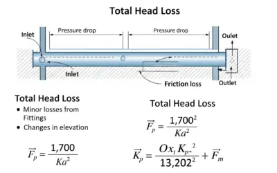
One of the major challenges in hydraulic engineering is transporting water over long distances efficiently. To do this, it's crucial to calculate the energy lost to friction as the water moves against the pipe walls. This energy loss, called head lossThe reduction in pressure or energy of a fluid due to friction in a pipe. It is measured in feet of water column (ft) or pressure units (psi, Pascals)., must be overcome by a pump. The Hazen-Williams formula is an empirical tool widely used by engineers to estimate these losses in pressurized water networks.
Pedagogical Note: This exercise will allow you to apply a concrete engineering formula to a realistic sizing problem. Mastering units and interpreting the results is just as important as the calculation itself.
Learning Objectives
- Understand and define the concept of linear head loss.
- Correctly apply the Hazen-Williams formula to a practical case.
- Master the conversion of common hydraulic units (flow rate, diameter).
- Interpret a calculation result to validate a technical choice.
Study Data
Installation Diagram
| Characteristic | Symbol | Value |
|---|---|---|
| Required flow rate for the town | \(Q\) | 700 \(\text{GPM}\) (Gallons Per Minute) |
| Pipe length | \(L\) | 8,500 \(\text{ft}\) |
| Internal pipe diameter | \(D\) | 8 \(\text{inches}\) |
| Pipe material | - | PVC (Polyvinyl Chloride) |
| Roughness coefficient (Hazen-Williams) | \(C\) | 150 (for new PVC) |
Questions to Solve
- To use the formula in standard US Customary units (feet/seconds), convert the flow rate \(Q\) from GPM to \(\text{ft}^3/\text{s}\) (CFS) and the diameter \(D\) from \(\text{inches}\) to \(\text{feet}\).
- Calculate the water velocity \(V\) in the pipe in \(\text{ft}/\text{s}\).
- Calculate the linear head loss \(h_f\) in \(\text{feet of water column (ft)}\) using the Hazen-Williams formula.
- Express this head loss in \(\text{psi}\) (pounds per square inch). (Use the approximation \(1 \text{ psi} \approx 2.31 \text{ ft of water}\)).
- The pump study recommends a pump capable of providing 25 \(\text{psi}\) to overcome friction. Is this choice validated by your calculation? (Neglect other "minor" losses).
Basics: The Hazen-Williams Formula
The Hazen-Williams formula is an empirical relationship that links the flow rate of water in a pipe to its physical and geometric properties. It is particularly well-suited for calculating head loss for water under pressure in pipes with diameters greater than 2 inches and at typical velocities.
Hazen-Williams Formula (US Customary Units)
The formula to calculate head loss (\(h_f\)) in feet is as follows (when \(Q\) is in CFS and \(D\) is in feet):
Note on Units: Be very careful! Other forms of this formula exist for different units (e.g., \(Q\) in GPM and \(D\) in inches). The constant (4.73) is specific to the units listed above (CFS and feet).
Solution: Head Loss Calculation with Hazen-Williams
Question 1: Unit Conversion
Principle
The first step in any physics or engineering calculation is to ensure all data is in a consistent unit system. The Hazen-Williams formula we are using is calibrated for US Customary Units (feet, seconds).
Mini-Lesson
In US engineering, flow rate is often discussed in Gallons Per Minute (GPM) for pumps and systems, but many core physics formulas (like this one) require Cubic Feet per Second (CFS). Similarly, pipe diameters are sold in "inches" but must be converted to "feet" for calculations.
Pedagogical Note
Always get in the habit of listing your data and converting it BEFORE starting any calculations. This prevents 90% of simple mistakes and structures your reasoning.
Standards
The American Water Works Association (AWWA) standards and engineering handbooks provide these conversion factors as standard practice.
Formula(s)
Flow Rate Conversion
Length Conversion
Assumptions
No assumptions are needed for a simple unit conversion.
Given Data
The input data for this question is from the problem statement:
| Parameter | Initial Value | Initial Unit |
|---|---|---|
| Flow Rate | 700 | \(\text{GPM}\) |
| Diameter | 8 | \(\text{inches}\) |
Tips
To convert GPM to CFS, divide by 448.8 (or multiply by 0.002228). To convert inches to feet, divide by 12. These should become quick reflexes!
Diagram (Before Calculation)
Unit Conversion
Calculation(s)
Flow Rate Conversion (\(Q\))
We start by converting the flow rate from Gallons Per Minute (GPM) to Cubic Feet per Second (CFS) by dividing by 448.8.
The value 1.559 \(\text{ft}^3/\text{s}\) will be used for all subsequent calculations.
Diameter Conversion (\(D\))
Next, we convert the diameter from \(\text{inches}\) to \(\text{feet}\) by dividing by 12.
The diameter is 0.667 \(\text{ft}\).
Diagram (After Calculation)
Converted Units
Reflections
The values \(Q \approx 1.559 \text{ CFS}\) and \(D = 0.667 \text{ ft}\) are now ready to be plugged into the physics formulas that follow.
Points of Vigilance
Be careful not to mix up unit systems. Using GPM or inches directly in a formula calibrated for CFS and feet will lead to a completely wrong answer.
Key Takeaways
- Unit consistency is the foundation of any reliable calculation.
- Always use the base US Customary units (feet, seconds) for this formula unless the formula constant is specifically adapted.
Did you know?
The unit "GPM" (Gallons Per Minute) is the most common way pumps are specified and sold in the United States. "CFS" (Cubic Feet per Second) is more common in civil engineering and large-scale water management (like rivers).
FAQ
Final Result
Try it yourself
If the flow rate was 900 GPM, what is its value in CFS? (Hint: 900 / 448.8)
Question 2: Calculate Water Velocity
Principle
The average velocity of a fluid in a pipe is the ratio of the volumetric flow rate to the cross-sectional area of the pipe. This is an important figure to check that the flow is not too slow (risk of sedimentation) or too fast (risk of erosion and noise).
Mini-Lesson
The conservation of mass for an incompressible fluid requires the flow rate (\(Q\)) to be constant. Since \(Q = V \times A\), if the cross-sectional area \(A\) decreases, the velocity \(V\) must increase, and vice-versa. This is called the continuity equation.
Pedagogical Note
Calculating the velocity is an excellent way to check the consistency of your unit conversions. A velocity of 50 ft/s in a water pipe is usually a sign of an error! Typical velocities are between 2 and 8 ft/s.
Standards
Water supply regulations and best practice guides recommend velocity ranges to limit erosion risks (high velocity) and sediment deposits (low velocity).
Formula(s)
Velocity-Flow Rate Relation
Area of a Circular Section
Assumptions
We assume the pipe is flowing full and the velocity is uniform across the entire cross-section (average velocity).
Given Data
| Parameter | Symbol | Value | Unit |
|---|---|---|---|
| Flow Rate | \(Q\) | 1.559 | \(\text{ft}^3/\text{s}\) |
| Diameter | \(D\) | 0.667 | \(\text{ft}\) |
Tips
To quickly calculate the area, remember that \( \pi/4 \approx 0.785 \). So, \( A \approx 0.785 \cdot D^2 \).
Diagram (Before Calculation)
Pipe Cross-Section
Calculation(s)
Area Calculation (\(A\))
To find the velocity, we first need the pipe's cross-sectional area. We use the formula for the area of a circle \(A = \pi \cdot D^2 / 4\), with \(D\) in feet.
The area of the pipe is approximately 0.349 \(\text{ft}^2\).
Velocity Calculation (\(V\))
Now that we have the flow rate in \(\text{ft}^3/\text{s}\) (CFS) and the area in \(\text{ft}^2\), we can divide them to find the velocity \(V = Q / A\).
The water velocity is 4.47 \(\text{ft/s}\), which is a very reasonable value for this type of system.
Diagram (After Calculation)
Average Velocity Profile
Reflections
A velocity of 4.47 ft/s is perfectly standard for this type of installation. It's high enough to prevent sediment from settling but not so high as to cause premature wear on the PVC pipe. The result is coherent.
Points of Vigilance
The classic mistake is forgetting to square the diameter in the area formula (\(D^2\)). Always double-check that your area unit is in \(\text{ft}^2\).
Key Takeaways
- Velocity is inversely proportional to the square of the diameter (\(V \propto 1/D^2\)). A small change in diameter has a huge impact on velocity.
Did you know?
In sewer lines, a minimum "self-cleaning" velocity (around 2 ft/s) is required to ensure the flow can carry suspended solids and prevent clogs.
FAQ
Final Result
Try it yourself
If the diameter was 16 inches and the flow rate 2.25 \(\text{ft}^3/\text{s}\), what would the approximate velocity be in \(\text{ft/s}\)?
Question 3: Calculate Head Loss (\(h_f\))
Principle
We will directly apply the Hazen-Williams formula using the data from the problem, which has been converted to the correct units. The calculation involves non-integer powers, requiring a calculator.
Mini-Lesson
The linear head loss \(h_f\) represents the energy dissipated by friction per unit weight of the fluid over a given length. It is directly proportional to the pipe length and increases very rapidly with the flow rate (raised to the 1.852 power), but it decreases even more rapidly as the diameter increases (raised to the 4.87 power).
Pedagogical Note
Break down the calculation: first, calculate the numerator, then the denominator. Only perform the final division at the end. This limits calculator entry errors and makes it easier to check the intermediate orders of magnitude.
Standards
The Hazen-Williams formula is a recognized empirical method widely used in design standards and guides for drinking water networks, especially in North America.
Formula(s)
Hazen-Williams Formula (USCU, ft/s)
Assumptions
The formula is applied assuming a turbulent flow regime and a water temperature around 60°F (15°C), conditions for which it is most accurate.
Given Data
| Parameter | Symbol | Value | Unit |
|---|---|---|---|
| Length | \(L\) | 8500 | \(\text{ft}\) |
| Flow Rate | \(Q\) | 1.559 | \(\text{ft}^3/\text{s}\) |
| Coefficient | \(C\) | 150 | - |
| Diameter | \(D\) | 0.667 | \(\text{ft}\) |
Tips
Without a scientific calculator, it's very difficult to compute non-integer powers. On an exam, these intermediate values (\(Q^{1.852}\), etc.) are often given.
Diagram (Before Calculation)
Installation Diagram
Calculation(s)
Formula Reminder
We will use the Hazen-Williams formula provided earlier.
To simplify, we'll calculate the complex terms separately: \(Q^{1.852}\), \(C^{1.852}\), and \(D^{4.87}\).
Flow Rate Term (\(Q^{1.852}\))
Raise the flow rate (in CFS) to the 1.852 power.
This value represents the flow's influence on the head loss.
Roughness Term (\(C^{1.852}\))
Do the same for the roughness coefficient C.
This value is in the denominator; the larger C is (smoother pipe), the larger this value, and the lower the head loss.
Diameter Term (\(D^{4.87}\))
Finally, raise the diameter (in feet) to the 4.87 power. This is the largest exponent, showing the significant impact of diameter.
This small value in the denominator will greatly increase the head loss.
Numerator Calculation
Now, let's assemble the numerator of the main formula: \(4.73 \cdot L \cdot Q^{1.852}\).
The numerator has a value of 89,035.
Denominator Calculation
Next, let's assemble the denominator: \(C^{1.852} \cdot D^{4.87}\).
The denominator has a value of 1,892.
Final Head Loss Calculation (\(h_f\))
Finally, divide the numerator by the denominator to get the total head loss in feet of water column.
The total linear head loss over 8,500 ft is 47.06 \(\text{ft}\).
Diagram (After Calculation)
Hydraulic Grade Line (HGL) Visualization
Reflections
A loss of 47.06 feet means that the water's energy level drops by over 47 feet across the 8500 ft of pipe. This is a significant energy loss that must be overcome by a pump or a sufficient elevation difference (gravity).
Points of Vigilance
The most common error in this calculation is forgetting to raise the C and D terms to their required powers. Be sure to use your calculator's power function (\(x^y\)) correctly for each term.
Key Takeaways
Head loss is one of the most critical parameters in designing a hydraulic network. It determines the required pump head (pressure) and, therefore, its energy consumption.
Did you know?
Other formulas exist for calculating head loss, such as the Darcy-Weisbach equation. It is more physically general but requires calculating a friction factor (ƒ) iteratively, making it more complex to use without software.
FAQ
Final Result
Try it yourself
For a flow \(Q=1.0 \text{ CFS}\), a diameter \(D=8 \text{ in}\), a length \(L=3000 \text{ ft}\) and a \(C=140\), what is the head loss \(h_f\) in \(\text{ft}\)?
Question 4: Convert Head Loss to PSI
Principle
Feet of water column (ft) and pounds per square inch (psi) are two different units for pressure. The conversion between them is an approximate constant based on the acceleration of gravity and the density of water.
Mini-Lesson
The pressure exerted by a column of water is given by the hydrostatic formula \(P = \rho \cdot g \cdot h\). For \(h=2.31 \text{ ft}\) (or 27.7 inches), with the density of water, this calculates to 1 pound of force on 1 square inch, or 1 psi.
Pedagogical Note
Hydraulic engineers often speak in "feet of head" because it directly compares pressure loss to elevation changes on a site profile. System operators often prefer "psi" because that's the unit displayed on pressure gauges.
Standards
Plumbing and waterworks standards specify minimum service pressures at the tap, often expressed in psi (e.g., 40 psi).
Formula(s)
Pressure Conversion Formula
Assumptions
We use the conventional value of 2.31 ft of water for 1 psi, which is a sufficient approximation for most common engineering calculations.
Given Data
| Parameter | Symbol | Value | Unit |
|---|---|---|---|
| Head Loss | \(h_f\) | 47.06 | \(\text{ft}\) |
Tips
For a quick estimate, you can divide by 2.3 (or multiply by 0.433). It's less precise but gives a good order of magnitude.
Diagram (Before Calculation)
Pressure Equivalence
Calculation(s)
Equivalent Pressure Calculation
To convert from feet of water column (ft) to pounds per square inch (psi), we use the conversion factor \(1 \text{ psi} \approx 2.31 \text{ ft}\). Therefore, we must divide the head loss in feet by 2.31.
The head loss of 47.06 \(\text{ft}\) is equivalent to a pressure loss of 20.37 \(\text{psi}\).
Diagram (After Calculation)
Pressure Equivalence - Result
Reflections
A loss of 20.37 psi is significant. If the pressure at the start of the pipe is 60 psi, only \(60 - 20.37 = 39.63 \text{ psi}\) will remain at the destination (not accounting for elevation changes).
Points of Vigilance
Don't confuse absolute pressure and gauge pressure. The "psi" on gauges (psig) is relative pressure (above atmospheric pressure). Head loss calculations deal with this gauge pressure.
Key Takeaways
The conversion factor \(1 \text{ psi} \approx 2.31 \text{ ft}\) is a fundamental value to memorize for any technician or engineer working with water systems in the US.
Did you know?
The unit "psi" (Pounds per Square Inch) is the most common measure of pressure in the United States, from car tires to water systems. Most of the world uses "bar" or "kiloPascals (kPa)".
FAQ
Final Result
Try it yourself
If the head loss is 11.55 \(\text{ft}\), how many psi is that?
Question 5: Validating the Pump Choice
Principle
For the system to work, the pump must provide a pressure at least equal to the sum of all head losses and the static head (elevation change). Here, we are just comparing the pump's capability to the friction loss calculated.
Mini-Lesson
A pump doesn't "create" pressure; it provides energy to the fluid, which increases its pressure. This pressure increase must be sufficient to (1) overcome friction (head loss) and (2) lift the water to the desired elevation (static head).
Pedagogical Note
In engineering, we always include a safety margin. Even though the calculation shows 20.37 psi is needed, choosing a 25 psi pump is good practice. It allows for future pipe aging (which increases losses) or a future increase in water demand.
Standards
Pump station design standards require safety factors on calculations to ensure the reliability and longevity of the installation.
Formula(s)
Validation Criterion
Assumptions
We are neglecting all other losses ("minor losses" from fittings, valves, etc.) and not accounting for the elevation difference, as requested in the problem.
Given Data
| Parameter | Symbol | Value | Unit |
|---|---|---|---|
| Calculated pressure to overcome | \(P_{\text{loss}}\) | 20.37 | \(\text{psi}\) |
| Available pressure (pump) | \(P_{\text{pump}}\) | 25 | \(\text{psi}\) |
Tips
No special trick for this comparison.
Diagram (Before Calculation)
Comparison: Pump vs. Losses
Calculation(s)
Pressure Comparison
We compare the pressure the pump can supply (\(P_{\text{pump}}\)) to the pressure needed to overcome friction (\(P_{\text{loss}}\)). The pump must be stronger than the losses.
Since 25 is greater than 20.37, the pump is adequate.
Margin Calculation
Let's calculate the safety margin, which is the "extra" pressure the pump provides beyond what's needed for friction.
The pump provides 4.63 \(\text{psi}\) more than needed for friction. This margin can cover the minor losses (from bends, valves) not calculated here.
Diagram (After Calculation)
Validation
Reflections
The condition is met. The pump has a pressure margin of \(25 - 20.37 = 4.63 \text{ psi}\), which is about 10.7 feet of head. This is a comfortable margin that ensures proper system operation even with minor variations.
Points of Vigilance
Never undersize a pump. A pump that is too weak will not achieve the required flow rate, or it will operate outside its best efficiency point (BEP), leading to wasted electricity and premature wear.
Key Takeaways
The head loss calculation is the key step that allows for the correct sizing of a pump in a water distribution network.
Did you know?
In a real project, you would also need to add "minor losses" (from fittings, valves, etc.) and the "static head" (the elevation difference between the pump and the delivery point). The pump must overcome the sum of all these! The 4.63 psi margin would be used to help cover these other losses.
FAQ
Final Result
Try it yourself
If the head loss is 20 psi and the pump provides 28 psi, what is the remaining pressure margin in psi?
Interactive Tool: Head Loss Simulator
Use the sliders to see how flow rate and pipe diameter impact head loss and water velocity. Calculations are for a 3000 ft long PVC pipe (C=150).
Input Parameters
Key Results (for L=3000ft, C=150)
Final Quiz: Test Your Knowledge
1. What does the coefficient C represent in the Hazen-Williams formula?
2. If a pipe's diameter is doubled (while keeping the same flow rate), how does the head loss change, approximately?
3. For which fluid is the Hazen-Williams formula most accurate?
4. Among these materials, which one generally has the highest Hazen-Williams C-factor (and thus the lowest friction loss)?
5. A head loss of 46.2 feet of water column (ft) is approximately equivalent to:
Glossary
- Head Loss
- The reduction in the total energy of a fluid (usually expressed as height of fluid column or pressure) as it flows through a pipe, primarily due to friction.
- Roughness Coefficient (C)
- A dimensionless empirical value that characterizes the surface condition of a pipe's interior. A high C-value corresponds to a smooth wall (low losses), while a low C-value corresponds to a rough wall (high losses).
- Turbulent Flow
- A type of fluid flow characterized by chaotic particle paths and eddies. This is the most common flow regime in hydraulic applications, for which the Hazen-Williams formula is designed.

0 Comments