Pump Station Bypass Line Design
Context: Hydraulic NetworksThe study of pressurized pipe systems used to move fluids, such as water distribution or collection networks..
A municipal pump station needs a bypass line to maintain service during pump maintenance. This bypass will connect the station's suction manifold (Point A) to its discharge manifold (Point B). Water will flow through the bypass driven only by the pressure difference between these two points. Your task is to analyze the flow through a proposed bypass pipe and determine if its design is safe and compliant with standard engineering guidelines.
Pedagogical Note: This exercise will teach you to apply the Hazen-Williams equationAn empirical formula used to calculate head loss due to friction in pipes, commonly used in water system design in the US. in a practical context, converting system pressures into flow rate (Q) and velocity (V).
Learning Objectives
- Convert pressure (PSI) to head (feet).
- Calculate friction loss per foot of pipe (Hydraulic Slope).
- Apply the Hazen-Williams equation (US Customary) to find flow rate (Q).
- Use the continuity equation to find flow velocity (V).
- Analyze and validate an engineering design against safety guidelines.
Study Data
System Specifications
| Characteristic | Value |
|---|---|
| Suction Manifold Pressure (Point A) | 60 PSI |
| Discharge Manifold Pressure (Point B) | 50 PSI |
| Maximum Design Velocity (Guideline) | 8 ft/s |
System Schematic
| Parameter | Symbol | Value | Unit |
|---|---|---|---|
| Bypass Pipe Length | \(L\) | 300 | ft |
| Bypass Pipe Diameter | \(d\) | 8 | in |
| Hazen-Williams C-Factor (PVC) | \(C\) | 150 | (dimensionless) |
Questions to Address
- Calculate the available pressure drop (\(\Delta P\)) in PSI and convert it to head loss (\(h_f\)) in feet.
- Define the Hazen-Williams formula for flow (Q) in US Customary Units and explain each component.
- Using the Hazen-Williams formula, calculate the flow rate (Q) in Gallons Per Minute (GPM) through the 8-inch bypass line.
- Calculate the flow velocity (V) in feet per second (ft/s) inside the bypass pipe.
- Compare the calculated velocity to the 8 ft/s guideline. Is this design acceptable? Explain why or why not.
Fundamentals of Pressurized Flow (Hazen-Williams)
To solve this problem, we must relate pressure, head loss, pipe properties, and flow. The two key concepts are the conversion of pressure to head and the Hazen-Williams equation for friction loss.
1. Pressure to Head Conversion
In fluid dynamics, headThe height of a column of fluid that would exert a given pressure at its base. A common way to express energy in hydraulic systems. is a measure of energy. Pressure (PSI) can be converted to head (feet of water) using a standard conversion factor. This tells us the "elevation" of water that would create that same pressure.
\[ h_f \text{ (ft)} = \frac{P \text{ (psi)}}{0.433 \text{ psi/ft}} \]
2. Hazen-Williams Equation (US Customary)
This is the standard empirical formula used in the United States for designing water mains. It relates flow rate (Q) to the pipe's properties and the hydraulic slopeThe head loss per unit length of pipe (ft/ft). It represents the "steepness" of the energy grade line. (S).
\[ Q = 0.281 \times C \times d^{2.63} \times S^{0.54} \]
Where:
- \(Q\) = Flow Rate in Gallons Per Minute (GPM)
- \(C\) = Hazen-Williams C-Factor (pipe roughness)
- \(d\) = Pipe Diameter in inches
- \(S\) = Hydraulic Slope (\(h_f / L\)) in ft/ft
Solution: Pump Station Bypass Line Design
Question 1: Calculate the available pressure drop (\(\Delta P\)) in PSI and convert it to head loss (\(h_f\)) in feet.
Principle
Flow in a pipe is driven by a difference in energy, not just pressure. We must first find the net pressure difference (\(\Delta P\)) between the start (Point A) and end (Point B) of the bypass. Then, we must convert this pressure energy into potential energy, or "head" (\(h_f\)), which is expressed in feet of water. This \(h_f\) value represents the total energy available to overcome friction in the pipe.
Mini-Lesson
Pressure vs. Head: Pressure (PSI, or lb/in²) is a force per unit area. Head (ft) is a height. For water, a column 1 foot high exerts 0.433 PSI at its base. Therefore, 1 PSI is equivalent to 1 / 0.433 = 2.31 feet of head. The total friction loss in a pipe (\(h_f\)) must be equal to the total head available to drive the flow.
Pedagogical Note
Think of this like a water slide. The pressure difference (\(\Delta P\)) is the total "push" available. The head loss (\(h_f\)) is the vertical height of the slide. You can't calculate the speed (flow) without first knowing the height (head) of the slide.
Norms
This calculation follows first principles of fluid mechanics. The conversion factor 0.433 psi/ft is based on the specific weight of water (62.4 lb/ft³) divided by 144 in²/ft².
Formula(s)
We will use two formulas.
Pressure Drop
Pressure to Head Conversion (US Customary)
Hypotheses
We make the following assumptions for this calculation.
- The fluid is water at a standard temperature.
- Points A and B are at the same elevation. (If they were not, we would also have to account for the static head difference).
- Minor losses from fittings (elbows, tees) are considered negligible for this initial calculation.
Data
We pull the following data points from the problem statement for this step.
| Parameter | Symbol | Value | Unit |
|---|---|---|---|
| Suction PressureThe pressure at the inlet side of the pump station (Point A). | \(P_A\) | 60 | PSI |
| Discharge Pressure | \(P_B\) | 50 | PSI |
Tips
A common mistake is using the absolute pressures (60 or 50) directly in the friction formula. Always remember that flow is caused by a pressure difference, so you must always calculate \(\Delta P\) first.
Schematic (Before Calculations)
The problem is to find the energy difference between Point A and Point B.
Energy at A vs. B
Calculation(s)
First, find the pressure drop in psi. Second, convert this value to feet of head.
Step 1: Calculate Pressure Drop
We subtract the lower pressure from the higher pressure:
Step 2: Convert Pressure Drop to Head Loss
Now, we convert this pressure drop to feet of head using the standard conversion factor:
Schematic (After Calculations)
The 10 PSI difference is equivalent to a 23.09 ft "drop" in energy, which will be consumed by friction.
Energy Grade Line (EGL)
Analysis
The available energy to push water through the 300-ft bypass pipe is 10 psi, which is equivalent to 23.09 feet of water head. This value, \(h_f\), is the total friction loss that will occur in the pipe as the water flows from A to B.
Cautionary Points
Be careful with units. The conversion 1 PSI = 2.31 ft (or 1 ft = 0.433 PSI) is only for water. Other fluids (like oil or gasoline) have different specific weights and different conversion factors.
Key Takeaways
- Flow is driven by a difference in energy (head).
- Pressure (PSI) is a force, Head (ft) is an energy level.
- For water, \(\Delta P \times 2.31 = h_f\).
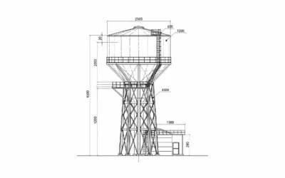
Did You Know?
This concept of "head" is why water towers work. A tank 100 ft in the air provides a static pressure of \(100 \text{ ft} \times 0.433 \text{ psi/ft} = 43.3 \text{ psi}\) to the homes below, all without a pump.
FAQ
Common follow-up questions for this step.
Final Result
Your Turn
If the suction pressure (A) was 70 psi and the discharge (B) was 55 psi, what would be the available head loss in feet?
Memo Card
Question 1 Summary:
- Key Concept: Pressure Head
- Essential Formula: \(h_f = (P_A - P_B) / 0.433\)
- Key Data: \(P_A = 60\), \(P_B = 50\)
Question 2: Define the Hazen-Williams formula for flow (Q) in US Customary Units and explain each component.
Principle
This question is purely theoretical. Its goal is to ensure we understand the tool we are about to use. The Hazen-Williams equation is an empirical formulaAn equation based on observation and experiment, not derived from pure theory. It works well but only under specific conditions., meaning it was developed from experiments, not theory. It is the most common formula used for modeling water distribution systems in the United States.
Formula(s)
The standard Hazen-Williams formula for flow (Q) in US Customary Units is:
Data
The components of the formula are defined as follows:
| Component | Symbol | Definition | Unit |
|---|---|---|---|
| Flow Rate | \(Q\) | The volume of water passing a point per unit time. | GPM |
| C-FactorA coefficient for pipe roughness. Higher C = smoother pipe. 150 (PVC) is very smooth, 100 (old iron) is rough. | \(C\) | Pipe roughness coefficient. | (dimensionless) |
| Pipe Diameter | \(d\) | The internal diameter of the pipe. | inches |
| Hydraulic SlopeThe head loss per unit length of pipe (ft/ft). | \(S\) | Friction loss per unit length (\(h_f / L\)). | ft/ft |
Cautionary Points
Do not use this formula for gases (like air) or highly viscous fluids (like heavy oil). It is specifically designed for water. Be careful with units: this formula only works when Q is in GPM, d is in inches, and S is in ft/ft.
Key Takeaways
- Formula: \(Q = 0.281 \times C \times d^{2.63} \times S^{0.54}\)
- Units are critical: Q (GPM), d (inches), S (ft/ft).
- This is an empirical formula for water only.
Final Result
Your Turn
If a pipe gets older and rougher, does its C-Factor go up or down? (Enter 1 for Up, 0 for Down).
Question 3: Using the Hazen-Williams formula, calculate the flow rate (Q) in Gallons Per Minute (GPM) through the 8-inch bypass line.
Principle
We will now combine the results from Q1 and the formula from Q2 to find the flow rate (Q). The head loss \(h_f\) (from Q1) and the pipe length \(L\) give us the hydraulic slope \(S\). With \(S\), \(C\), and \(d\) known, \(Q\) is the only unknown variable left.
Mini-Lesson
The calculation flow is: 1. Find Slope (S): \(S = h_f / L\). This calculates the "ft of head loss per ft of pipe". 2. Calculate Q: Plug \(S\), \(C\), and \(d\) into the Hazen-Williams formula. Pay close attention to the exponents (2.63 and 0.54), as they require a scientific calculator.
Pedagogical Note
This is where all the data comes together. The pressures (from Q1) define the *available energy*. The pipe properties (C, d, L) define the *resistance*. The formula finds the *balance point* between this energy and resistance, which is the resulting flow rate, Q.
Norms
Calculations follow the standard application of the Hazen-Williams formula per AWWA M11, "Steel Pipe—A Guide for Design and Installation".
Formula(s)
We will use two formulas, one to find the slope and one to find the flow.
Hydraulic Slope
Hazen-Williams Flow Equation
Hypotheses
We assume all conditions for the Hazen-Williams formula are met (water at 60°F, turbulent flow, d > 2in).
Data
We use data from the problem statement and the result from Q1.
| Parameter | Symbol | Value | Unit |
|---|---|---|---|
| Head Loss (from Q1) | \(h_f\) | 23.0942 | ft |
| Pipe Length | \(L\) | 300 | ft |
| C-Factor | \(C\) | 150 | (dimensionless) |
| Pipe Diameter | \(d\) | 8 | in |
Tips
To avoid calculator errors, solve the exponential parts (\(d^{2.63}\) and \(S^{0.54}\)) first. Write these intermediate values down, then multiply all the final numbers together. This is much more reliable than typing the entire equation at once.
Schematic (Before Calculations)
We are solving for Q by inputting all known properties into the formula.
Solving for Q
Calculation(s)
First, calculate the hydraulic slope \(S\). Then, solve for the intermediate exponential terms. Finally, combine everything to find Q.
Step 1: Calculate Hydraulic Slope (S)
This value represents the feet of head loss per foot of pipe. We use the more precise value of \(h_f\).
Step 2: Calculate Intermediate Terms
To prevent errors, we solve the exponential parts first. First, the diameter term:
Next, solve the slope term using the value from Step 1:
Step 3: Calculate Flow (Q)
Now, we assemble the full Hazen-Williams formula with all our components:
Schematic (After Calculations)
We have solved for the flow, Q.
Calculated Flow Rate
Analysis
The calculation shows that given a 10 PSI pressure drop (23.09 ft of head) over 300 ft, an 8-inch PVC (C=150) pipe will allow approximately 2379 Gallons Per Minute (GPM) to flow through it. This is a very high flow rate for an 8-inch pipe.
Cautionary Points
A tiny change in the C-Factor or diameter can have a huge effect. If the pipe was old iron (C=100) instead of PVC (C=150), the flow would only be \((100/150) \times 2379 = 1586 \text{ GPM}\). The diameter is even more sensitive due to the 2.63 exponent.
Key Takeaways
- First, find Slope: \(S = h_f / L\).
- Second, find intermediate terms: \(d^{2.63}\) and \(S^{0.54}\).
- Finally, combine all terms to find Q.
Did You Know?
A flow of 2379 GPM is equivalent to filling a standard 50,000-gallon swimming pool in just 21 minutes. This gives a sense of the large volume of water moving through this bypass pipe.
FAQ
Common follow-up questions for this step.
Final Result
Your Turn
If the pipe was 10-inch diameter (\(d=10\)) instead of 8-inch, the \(d^{2.63}\) term would be 426.6. What would the new flow rate (Q) be? (Use C=150, S^0.54=0.2310).
Memo Card
Question 3 Summary:
- Key Concept: Solving for Flow (Q)
- Essential Formula: \(S = h_f / L\), then \(Q = 0.281 \times C \times d^{2.63} \times S^{0.54}\)
- Key Data: \(h_f = 23.094\), \(L = 300\), \(C = 150\), \(d = 8\)
Question 4: Calculate the flow velocity (V) in feet per second (ft/s) inside the bypass pipe.
Principle
Now that we know the flow rate (Q, the *volume* of water) from Question 3, we need to find its velocity (V, the *speed*). We use the Continuity EquationThe principle that for an incompressible fluid, the flow rate (Q) is equal to the cross-sectional area (A) times the average velocity (V). Q = A * V., which relates flow rate, pipe area, and velocity. A standard conversion factor is used to handle the mixed units (GPM, inches, and ft/s).
Mini-Lesson
The base formula is \(Q = A \times V\). However, since Q is in GPM and pipe diameter is in inches, while we want V in ft/s, we use a pre-converted formula which is standard in US hydraulic engineering: \(V \text{ (ft/s)} = 0.4085 \times \frac{Q \text{ (GPM)}}{d^2 \text{ (in)}}\). This formula is a critical tool for any water system designer.
Pedagogical Note
Think of Q (flow) as the total number of cars passing a point on a highway. Think of V (velocity) as their speed. If you have 8 lanes (large diameter), the cars can go slower to get the same number through. If you squeeze them into 2 lanes (small diameter), they must go much faster. We are checking the "speed" of the water.
Norms
The formula \(V = 0.4085 \times Q/d^2\) is a standard conversion of the Continuity Equation, widely published in engineering manuals (like the AWWA M11).
Formula(s)
We will use the standard US Customary formula for velocity.
Velocity Equation (US Customary)
Hypotheses
We assume the flow (Q) is evenly distributed across the pipe's cross-sectional area (i.e., we are calculating the *average* velocity).
Data
We use the flow rate from Q3 and the diameter from the problem statement.
| Parameter | Symbol | Value | Unit |
|---|---|---|---|
| Flow Rate (from Q3) | \(Q\) | 2378.9 | GPM |
| Pipe Diameter | \(d\) | 8 | in |
Tips
The most common error is forgetting to square the diameter (\(d^2\)). Be sure to calculate \(d \times d\) for the denominator, not just \(d\). Also, make sure you are using diameter in inches, as required by the formula's constant (0.4085).
Schematic (Before Calculations)
We know the volume (Q) passing through the pipe area. We need to find the speed (V).
Finding Velocity (V)
Calculation(s)
Step 1: Calculate \(d^2\)
First, solve the denominator of the velocity formula, which is the diameter in inches, squared:
Step 2: Calculate Velocity (V)
Now, we use the velocity formula, substituting the flow (from Q3) and the \(d^2\) value:
Schematic (After Calculations)
The water is moving at an average speed of 15.18 feet every second.
Calculated Velocity
Analysis
A velocity of 15.18 ft/s is extremely high for a municipal water main. This indicates that the 8-inch pipe is significantly undersized for the available 10 psi pressure drop. This velocity creates a high risk of "water hammer" (surge) if a valve is closed quickly.
Cautionary Points
High velocity (over 8-10 ft/s) can cause water hammerA pressure surge or shockwave caused by a fluid in motion being forced to stop or change direction suddenly (e.g., a fast-closing valve)., which is a hydraulic shockwave that can break pipes and damage equipment. It's like a freight train hitting a wall. Lower velocity is almost always safer.
Key Takeaways
- Velocity is a critical design check.
- Formula: \(V = 0.4085 \times Q / d^2\).
- Units: V (ft/s), Q (GPM), d (inches).
- High velocity is dangerous.
Did You Know?
15.18 ft/s is over 10 miles per hour. While this doesn't sound fast for a car, for a dense, heavy fluid like water, it carries enormous momentum. Most designers aim for velocities between 3 and 7 ft/s in water mains.
FAQ
Common follow-up questions for this step.
Final Result
Your Turn
From the "Your Turn" in Q3: if the flow (Q) was 4172.9 GPM in a 10-inch pipe, what would be the new velocity (V)? (Note: \(d^2 = 100\)).
Memo Card
Question 4 Summary:
- Key Concept: Flow Velocity
- Essential Formula: \(V = 0.4085 \times Q / d^2\)
- Key Data: \(Q = 2378.9\), \(d = 8\)
Question 5: Compare the calculated velocity to the 8 ft/s guideline. Is this design acceptable? Explain why or why not.
Principle
This is the final analysis step, where we act as the engineer. We must compare our calculated value (V = 15.18 ft/s) against the client's requirement (V < 8 ft/s). This is a simple pass/fail check followed by a professional justification.
Mini-Lesson
Engineering design is an iterative process. 1. Propose: An 8-inch pipe. 2. Calculate: Find Q and V. 3. Analyze: Compare V to the guideline. 4. Conclude & Revise: The design fails (V is too high). The engineer must now propose a new design (e.g., a 10-inch or 12-inch pipe) and repeat the calculations.
Pedagogical Note
A calculation is just a number. The *analysis* is where the engineer earns their salary. You must be able to explain *what the number means* and *what to do about it*. Simply saying "15.18 > 8" is not a complete answer.
Norms
The 8 ft/s guideline (often 5-10 ft/s) is a standard "rule of thumb" in hydraulic design to prevent water hammer, minimize friction losses, and reduce pipe erosion. This guideline is published in most design manuals (e.t., Ten States Standards).
Formula(s)
We will use a simple percentage difference formula to quantify *how much* we failed the check.
Percentage Over Limit
Hypotheses
We assume the 8 ft/s guideline is a strict requirement for this project.
Data
We use the velocity from Q4 and the guideline from the problem statement.
| Parameter | Symbol | Value | Unit |
|---|---|---|---|
| Actual Velocity (from Q4) | \(V_{\text{actual}}\) | 15.18 | ft/s |
| Velocity Limit (Guideline) | \(V_{\text{limit}}\) | 8 | ft/s |
Tips
When presenting a "bad news" result like this, it's good practice to also suggest the solution. Stating "it's unacceptable" is good. Stating "it's unacceptable, and we should analyze a 10-inch or 12-inch pipe next" is much better.
Schematic (Before Calculations)
We are comparing our calculated velocity against the "safe" limit.
Velocity Check
Calculation(s)
We will use the standard percentage change formula to see how much our actual value exceeds the limit.
Analysis
The calculated velocity of 15.18 ft/s exceeds the 8 ft/s guideline by nearly 90%. This design is unacceptable. The high velocity would create a significant risk of water hammer (surge pressures) if a valve were closed, potentially damaging the manifolds or the pipe itself. It would also lead to high, localized friction losses at any fittings.
Cautionary Points
This is a common design failure. The 10 PSI pressure drop provides a large amount of energy, and the 8-inch pipe is simply too small to convey that much flow (2379 GPM) at a safe velocity. Never specify a design that is this far outside of established safety guidelines.
Key Takeaways
- The 8-inch pipe design is unsafe and unacceptable.
- Calculated velocity (15.18 ft/s) is almost 90% over the 8 ft/s limit.
- The solution is to use a larger pipe (e.g., 10-inch or 12-inch) to reduce the velocity.
Did You Know?
What would be the right pipe size? A 10-inch pipe (d=10) would give Q=4173 GPM and V=17.05 ft/s (still too high!). A 12-inch pipe (d=12) would give Q=6761 GPM and V=23.0 ft/s (even worse!). This tells us the *only* solution is to use a flow-control valve to *force* the flow to a lower rate, or that the 8 ft/s limit cannot be met with this pressure drop.
FAQ
Common follow-up questions for this step.
Final Result
Your Turn
If the velocity guideline was 10 ft/s instead of 8 ft/s, would the 8-inch pipe design be acceptable? (Enter 1 for Yes, 0 for No).
Memo Card
Question 5 Summary:
- Key Concept: Design Validation
- Essential Formula: \(V_{\text{actual}}\) vs. \(V_{\text{limit}}\)
- Conclusion: \(15.18 \text{ ft/s} \gg 8 \text{ ft/s}\). Design Fails.
Interactive Tool: Flow & Velocity Simulator
Use the sliders to see how changing the pipe diameter or roughness (C-Factor) would affect the flow (Q) and velocity (V). The head loss (\(h_f = 23.09 \text{ ft}\)) and length (\(L = 300 \text{ ft}\)) are fixed based on our problem.
Input Parameters
Key Requirements
Final Quiz: Test Your Knowledge
1. What is the primary reason for calculating head loss (\(h_f\)) from pressure drop (\(\Delta P\))?
2. In the Hazen-Williams formula, which variable has the largest impact on the flow (Q)?
3. Our 8-inch pipe design had a velocity of 15.18 ft/s (FAIL). What is the most common *engineering* solution to fix this?
Glossary
- C-Factor (Hazen-Williams)
- An empirical coefficient for pipe roughness. A higher C-Factor means a smoother pipe (e.g., PVC C=150). A lower C-Factor means a rougher pipe (e.g., old iron C=100), which causes more friction.
- Continuity Equation
- The principle (Q = A * V) that states flow rate (Q) is the product of the pipe's cross-sectional area (A) and the average flow velocity (V).
- Empirical Formula
- An equation based on observation and experimental data, not derived from pure theory. The Hazen-Williams formula is a prime example.
- Head (Hydraulic)
- A measure of energy in a fluid, expressed as a height (in feet or meters). It combines pressure head, elevation head, and velocity head.
- Head Loss (\(h_f\))
- The energy (head) "lost" or consumed by friction as fluid moves through a pipe. This is the energy that drives the flow.
- Hydraulic Slope (S)
- The rate of head loss per unit length of pipe (\(S = h_f / L\)). It is expressed in ft/ft or m/m.
- PSI (Pounds per Square Inch)
- A US Customary unit of pressure, or force per unit area. 1 PSI is equivalent to the pressure from a 2.31-foot column of water.
- Water Hammer (Surge)
- A dangerous pressure surge or shockwave caused by a fluid in motion (with high velocity) being forced to stop or change direction suddenly, such as by a fast-closing valve.

0 Comments