Calculating a Pump's Maximum Suction Head
Context: One of the biggest challenges in hydraulics is ensuring a pump operates correctly by avoiding the destructive phenomenon of cavitationThe formation of vapor bubbles in a liquid when the local pressure drops below its vapor pressure. The implosion of these bubbles can damage components..
This occurs when the pressure at the pump's inlet drops below the liquid's vapor pressure. To prevent it, it is crucial to calculate the maximum geometric height (or "suction lift") at which a pump can be placed above the free surface of the liquid. This exercise will guide you through calculating the NPSH AvailableNet Positive Suction Head Available (NPSHa). This is the absolute pressure head at the pump's inlet, above the liquid's vapor pressure. It is a characteristic of your system/installation. (NPSHa) of the installation to determine this maximum height.
Learning Note: This exercise will teach you to apply Bernoulli's equation to a real-world pumping system, accounting for pressures (head), velocity, and head loss to ensure a reliable and durable installation.
Learning Objectives
- Understand the phenomenon of cavitation and its causes.
- Define and differentiate NPSH Available (NPSHa) and NPSH RequiredNet Positive Suction Head Required (NPSHr). This is the minimum pressure head required at the pump's inlet to prevent cavitation. It is a characteristic provided by the pump manufacturer. (NPSHr).
- Calculate all components of NPSHa: pressure head, velocity head, and head losses.
- Determine the maximum geometric suction head for a given installation.
Problem Data
Pumping Installation Diagram
| Characteristic | Symbol | Value |
|---|---|---|
| Atmospheric Pressure | \(P_{\text{atm}}\) | 14.7 psi (at sea level) |
| Water Temperature | \(T\) | 70 °F |
| Pump NPSH Required | \(\text{NPSH}_r\) | 10.0 ft |
| Parameter | Symbol | Value | Unit |
|---|---|---|---|
| Volumetric Flow Rate | \(Q_v\) | 440 | GPM |
| Suction Pipe Diameter | \(D\) | 4.0 | in |
| Total Pipe Length | \(L\) | 25 | ft |
| Linear Head Loss Coefficient | \(\lambda\) | 0.02 | - |
Problem Questions
- Calculate the water velocity in the suction piping.
- Calculate the total head loss (\(\Delta H_T\)) in the suction piping.
- Write the literal equation for the NPSH Available (NPSHa) at the pump.
- Determine the maximum allowable suction head (\(H_{s, \text{max}}\)).
Fundamentals: NPSH and Cavitation
To solve this problem, we will rely on Bernoulli's equation and the definition of NPSH, all expressed in terms of "head" (feet of fluid).
1. Bernoulli's Equation (in terms of Head)
This expresses the conservation of energy for a moving fluid. Between the free surface of the reservoir (point 1) and the pump inlet (point 2), it is written:
\[ h_1 + \frac{v_1^2}{2g} + z_1 = h_2 + \frac{v_2^2}{2g} + z_2 + \Delta H_{\text{T}(1 \to 2)} \]
Where \(h\) is the pressure head (\(P/\gamma\)), \(v^2/2g\) is the velocity head, and \(z\) is the elevation head.
2. NPSH Available (NPSHa)
NPSHa represents the absolute energy head at the pump inlet above the liquid's vapor pressure head. It is calculated from the system's characteristics.
\[ \text{NPSH}_a = \frac{P_{\text{inlet, abs}}}{\gamma} - \frac{P_{\text{vapor}}}{\gamma} = \left( h_{\text{inlet, static}} + \frac{v_{\text{inlet}}^2}{2g} \right) - h_{\text{vapor}} \]
To prevent cavitation, it is essential that: \(\text{NPSH}_a > \text{NPSH}_r\). We will use a safety margin.
Solution: Calculating Maximum Suction Head
Question 1: Calculate the water velocity in the suction piping.
Principle
The velocity of the fluid in a pipe is directly related to the volumetric flow rate and the cross-sectional area of the pipe. This is a direct application of the conservation of mass (or flow rate) for an incompressible fluid.
Mini-Course
The continuity equation states that for an incompressible fluid, the volumetric flow rate (\(Q_v\)) is constant. This flow rate is the product of the pipe's cross-sectional area (\(A\)) and the average fluid velocity (\(v\)) through that section. Therefore, if we know the flow rate and the pipe geometry, we can find the velocity.
Pedagogical Note
The most critical step in this type of calculation is unit management. Flow rates are often in Gallons Per Minute (GPM) and diameters in inches (in). It is imperative to convert everything to standard US customary units (ft³/s and ft) before applying the formula to avoid errors.
Standards
This calculation is based on fundamental physics. However, many piping design standards (like ASME B31.3) recommend maximum velocities for fluids (typically 5-10 ft/s for water) to limit erosion, noise, and vibration.
Formula(s)
Velocity-Flow Rate Relation
Assumptions
- The fluid (water) is considered incompressible.
- The flow is steady (flow rate does not vary over time).
- The calculated velocity is an average velocity over the pipe's cross-section.
Given Data
We must first convert the units to be consistent (ft³/s and ft).
| Parameter | Symbol | Value | Unit | Conversion (US Customary) |
|---|---|---|---|---|
| Volumetric Flow Rate | \(Q_v\) | 440 | GPM | \(440 / (7.4805 \times 60) \approx 0.9804 \text{ ft}^3/\text{s}\) |
| Diameter | \(D\) | 4.0 | in | \(4.0 / 12 = 0.3333 \text{ ft}\) |
Tips
The conversion `1 GPM ≈ 0.002228 ft³/s` is useful, but it's often more intuitive to remember `1 ft³ ≈ 7.48 gal`. A velocity of 11.23 ft/s is quite high for a suction line, where velocities are typically kept below 5-7 ft/s to minimize head loss.
Diagram (Before Calculation)
Pipe Cross-Section
Calculation(s)
Step 1: Unit Conversion
First, convert all inputs to base US customary units (feet and seconds).
Step 2: Apply Velocity Formula
Now, we apply the continuity equation: \( v = \frac{4 \cdot Q_v}{\pi \cdot D^2} \).
Diagram (After Calculation)
Flow Visualization
Reflections
A velocity of 11.23 ft/s is quite high for a suction line, which suggests significant head loss will occur. In a real-world design, one might consider increasing the pipe diameter (e.g., to 5 or 6 inches) to reduce this velocity and thus increase the safety margin against cavitation.
Key Points
The most common mistake is forgetting to square the diameter in the formula. Another frequent error is mixing units (e.g., using inches and feet, or GPM and ft/s, in the same equation). Always convert to base units first.
Points to Remember
- Velocity is inversely proportional to the square of the diameter (\(v \propto 1/D^2\)).
- The continuity equation (\(Q_v=A \cdot v\)) is a fundamental tool.
- Correct unit conversion is the essential first step in any calculation.
Did you know?
The Irish engineer Osborne Reynolds, in the 19th century, conducted crucial experiments showing the transition between laminar (orderly) and turbulent (chaotic) flow. At 11.23 ft/s in a 4-inch pipe, this water flow is highly turbulent.
FAQ
Final Result
Try It Yourself
What flow rate (in GPM) would be required to keep the velocity at 7.0 ft/s in the same pipe?
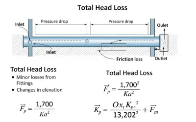
Question 2: Calculate the total head loss (\(\Delta H_{\text{T}}\)) in the suction piping.
Principle
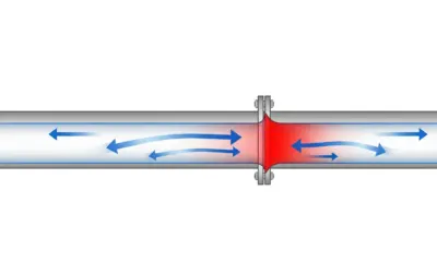
Head loss represents the energy "lost" by the fluid, converted into heat due to friction against the pipe walls (linear head loss) and turbulence from fittings like elbows or valves (minor head loss). Here, we are only calculating the linear (frictional) head loss for simplicity.
Mini-Course
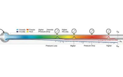
The Darcy-Weisbach equation is the standard formula for calculating linear head loss. It relates the head loss (\(\Delta H\)) to the fluid velocity (\(v\)), pipe diameter (\(D\)), and pipe length (\(L\)) via a dimensionless friction factor, \(\lambda\) (lambda), which depends on pipe roughness and the flow regime (Reynolds number).
Pedagogical Note
Note the dependence of head loss on the *square* of the velocity (\(v^2\)). This means if you double the flow rate (and thus velocity), you *quadruple* the frictional head loss! This is the most influential factor in hydraulic system design.
Standards
Calculating head loss is standard engineering practice. The friction factor \(\lambda\) is often determined using the Colebrook-White equation, which is the basis for the Moody diagram. These methods are recommended by many international standards for piping system design.
Formula(s)
Darcy-Weisbach Equation
Assumptions
- Only linear (friction) losses are considered (neglecting the reservoir exit, strainer, and elbow).
- The friction factor \(\lambda\) is constant along the entire pipe.
- The acceleration of gravity \(g\) is taken as 32.2 ft/s².
Given Data
We use the data from the problem and the result from Question 1.
| Parameter | Symbol | Value | Unit |
|---|---|---|---|
| Friction Factor | \(\lambda\) | 0.02 | - |
| Length | \(L\) | 25 | ft |
| Diameter | \(D\) | 0.3333 | ft |
| Velocity | \(v\) | 11.23 | ft/s |
Tips
The term \(v^2/(2g)\) is called the "velocity head." It's often useful to calculate it separately, as it reappears in many hydraulic calculations. Here, it is 1.958 ft, which is a significant value.
Diagram (Before Calculation)
Head Loss Visualization
Calculation(s)
Step 1: Calculate the Velocity Head (\(v^2/2g\))
This term represents the kinetic energy of the fluid, expressed in feet of head. We use the velocity from Q1 (\(v \approx 11.23 \text{ ft/s}\)) and \(g \approx 32.2 \text{ ft/s}^2\).
Step 2: Calculate the Head Loss (\(\Delta H_{\text{T}}\))
We now apply the Darcy-Weisbach formula using our known values: \(\lambda = 0.02\), \(L = 25 \text{ ft}\), \(D = 0.3333 \text{ ft}\), and the velocity head (\(v^2/2g \approx 1.958 \text{ ft}\)).
We have therefore lost approximately 2.94 feet of head (energy) due to friction over the 25-foot pipe. This value will be subtracted from the available energy at the suction.
Diagram (After Calculation)
Energy Loss Illustration
Reflections
Losing almost 3 feet of head over just 25 feet of pipe confirms that our velocity of 11.23 ft/s is high and has a major impact. In a real-world scenario, minor losses (from the strainer, elbow, etc.) would add to this figure, further reducing the possible suction height.
Key Points
Don't forget the acceleration of gravity, \(g\), in the velocity head term. Ensure that \(L\) and \(D\) are in the same unit (feet) so the ratio \(L/D\) is dimensionless. The result \(\Delta H_T\) is a height, so its unit is feet.
Points to Remember
- Head loss is an energy "tax" for moving fluid.
- The Darcy-Weisbach equation is the standard tool for linear losses.
- Head loss increases with length and velocity, and decreases with diameter.
Did you know?
The Moody diagram, developed in 1944 by Lewis Ferry Moody, is a graph that plots the friction factor \(\lambda\) against the Reynolds number and the relative roughness of the pipe. Before calculators, this diagram was an essential tool for all fluid mechanics engineers.
FAQ
Final Result
Try It Yourself
Keeping the same velocity, what would the head loss be if the pipe were 50 ft long?
Question 3: Write the literal equation for the NPSH Available (NPSHa).
Principle
NPSHa is determined by applying the Bernoulli energy balance equation between the liquid surface in the reservoir (where conditions are known) and the pump inlet (the point of interest). It represents the total absolute head available at the suction, minus the vapor pressure head.
Mini-Course
Bernoulli's equation is key: \(h_1 + \frac{v_1^2}{2g} + z_1 = h_2 + \frac{v_2^2}{2g} + z_2 + \Delta H_{\text{T}}\). The definition of NPSHa is \(\text{NPSH}_a = h_2 + \frac{v_2^2}{2g} - h_v\). The method is to isolate the term for the total energy at the inlet, \(\left( h_2 + \frac{v_2^2}{2g} \right)\), from Bernoulli's, and substitute it into the NPSHa definition.
Pedagogical Note
The choice of points 1 and 2 is strategic. We always choose a point 1 where we know the most information (here, the surface of a large reservoir at atmospheric pressure with zero velocity) to simplify the equation and easily isolate the unknown at point 2.
Standards
Applying Bernoulli's equation is a fundamental law of physics. The definitions of NPSH are standardized by organizations like the Hydraulic Institute (HI), ensuring all engineers and manufacturers use the same terminology.
Formula(s)
Bernoulli's Equation (Head)
Definition of NPSH Available
Assumptions
- The pressure head at the reservoir surface (point 1) is the atmospheric pressure head (\(h_1 = h_{\text{atm}} = P_{\text{atm}}/\gamma\)).
- The velocity at the surface of a large reservoir is considered negligible (\(v_1 \approx 0\)).
- We set the reference elevation \(z=0\) at the water surface, so \(z_1=0\). The pump inlet is at an elevation \(z_2 = H_s\).
Given Data
This is a literal derivation, so the data consists of the symbols: \(h_{\text{atm}}, h_v, g, H_s, v, \Delta H_{\text{T}}\).
Tips
Think of NPSHa as an energy "budget." The source is the atmospheric pressure head (\(h_{\text{atm}}\)). You "spend" this budget by lifting the water (\(H_s\)) and overcoming friction (\(\Delta H_T\)). What remains must be greater than the liquid's vapor pressure head (\(h_v\)) plus the pump's requirement (\(\text{NPSH}_r\)).
Diagram (Before Calculation)
Points for Bernoulli's Equation
Calculation(s)
Step 1: Simplify Bernoulli's Equation
We apply our assumptions (\(h_1 = h_{\text{atm}}\), \(v_1 = 0\), \(z_1 = 0\), \(z_2 = H_s\)) to the main equation:
Step 2: Isolate the Total Inlet Head
The definition of NPSHa uses the term \(\left( h_2 + \frac{v_2^2}{2g} \right)\), which is the total head at the pump inlet. Let's solve for this term:
Step 3: Substitute into the NPSHa Definition
Now we replace the \(\left( h_2 + \frac{v_2^2}{2g} \right)\) term in the NPSHa definition: \(\text{NPSH}_a = \left( h_2 + \frac{v_2^2}{2g} \right) - h_v\)
Rearranging for clarity gives the final, fundamental equation:
This equation shows that the NPSH Available is the atmospheric head, minus the vapor pressure head, minus the static lift, minus the friction losses.
Diagram (After Calculation)
Head Balance Diagram
Reflections
This final equation is fundamental. It clearly shows that NPSHa (the system's contribution) decreases if: the suction head \(H_s\) increases, the head loss \(\Delta H_T\) increases (longer pipe, higher velocity), atmospheric pressure \(h_{\text{atm}}\) decreases (high altitude), or vapor pressure \(h_v\) increases (hotter liquid).
Key Points
Be careful not to confuse terms. \(H_s\) is a geometric elevation, while all other terms (\(h_{\text{atm}}\), \(h_v\), \(\Delta H_T\)) are energy heads. Maintaining consistent signs and units (all in feet) is crucial throughout the derivation.
Points to Remember
\(\text{NPSH}_a\) = (Absolute Source Pressure Head) - (Geometric Lift) - (Total Head Losses). This is the energy balance for the suction line.
Did you know?
Evangelista Torricelli's work on the barometer in the 17th century first demonstrated that the atmosphere has weight and exerts pressure. It is this atmospheric pressure (head) that "pushes" the water up into the pump. A pump doesn't "suck"; it creates a low-pressure zone, and the atmosphere pushes the fluid in.
FAQ
Final Result
Try It Yourself
If the reservoir was closed and pressurized to a head of \(h_{\text{res}}\), how would the equation change? (replace the incorrect term)
Question 4: Determine the maximum allowable suction head (\(H_{s, \text{max}}\)).
Principle
The maximum height is reached at the physical limit of correct operation, i.e., just before cavitation begins. This condition is defined when the NPSH Available from the system is exactly equal to the NPSH Required by the pump, plus a safety margin to cover uncertainties.
Mini-Course
The \(\text{NPSH}_r\) is an intrinsic characteristic of the pump, provided by the manufacturer. It represents the minimum energy head the fluid must have at the inlet for the pump to operate without cavitating. Calculating \(H_{s, \text{max}}\) involves using the \(\text{NPSH}_a\) equation from Q3, setting \(\text{NPSH}_a = \text{NPSH}_r + \text{Margin}\), and then solving for the unknown \(H_s\).
Pedagogical Note
This calculation is the culmination of the exercise. It transforms a series of theoretical principles (Bernoulli, head loss) into a concrete, practical value for an installer: "Do not place the pump more than X feet above the water." This is the essence of engineering design.
Standards
The Hydraulic Institute (HI) is a primary reference for this. Their standards, like ANSI/HI 9.6.1, recommend safety margins between NPSHa and NPSHr. A margin of 2-3 feet is common practice, but it may be larger for critical applications or difficult liquids.
Formula(s)
Cavitation Limit Condition
Maximum Suction Head Equation
Assumptions
- The provided data (flow rate, NPSHr, fluid properties) are accurate for the operating conditions.
- We will use a conservative safety margin of **2.0 ft**.
Given Data
We need the properties of water at 70°F and the results from the previous questions.
| Parameter | Symbol | Value | Unit |
|---|---|---|---|
| Atmospheric Pressure | \(P_{\text{atm}}\) | 14.7 | psi |
| Vapor Pressure of Water (70°F) | \(P_v\) | 0.363 | psi |
| Specific Weight of Water (70°F) | \(\gamma\) | 62.3 | lb/ft³ |
| Head Loss | \(\Delta H_{\text{T}}\) | 2.937 | ft |
| NPSH Required | \(\text{NPSH}_r\) | 10.0 | ft |
| Safety Margin | \(\text{Margin}\) | 2.0 | ft |
Tips
The term \(h_{\text{atm}}\) (atmospheric head) is the theoretical maximum height water can be lifted by a perfect vacuum at sea level. \(h_{\text{atm}} = P_{\text{atm}}/\gamma = (14.7 \times 144) / 62.3 \approx 33.95 \text{ ft}\). All "expenses" (vapor pressure, friction, pump requirement) are subtracted from this total budget.
Diagram (Before Calculation)
Head Budget Balance
Calculation(s)
Step 1: Calculate Net Pressure Head Available
This is the term \((h_{\text{atm}} - h_v)\). It represents the maximum head the atmosphere can provide, accounting for the liquid's tendency to boil.
- \(P_{\text{atm}} = 14.7 \text{ psi}\)
- \(P_v = 0.363 \text{ psi}\)
- \(\gamma = 62.3 \text{ lb/ft}^3\)
- Conversion: \(1 \text{ psi} = 144 \text{ lb/ft}^2\) (psf)
First, let's find the head for each pressure term:
The net pressure head is:
Step 2: Calculate Maximum Suction Head (\(H_{s, \text{max}}\))
We now use the final formula, subtracting all "costs" from our available net pressure head:
Substitute all our values:
- Net Pressure Head \((h_{\text{atm}} - h_v)\) = 33.14 ft (from Step 1)
- \(\Delta H_{\text{T}} = 2.937 \text{ ft}\) (from Question 2)
- \(\text{NPSH}_r = 10.0 \text{ ft}\) (Given)
- \(\text{Margin} = 2.0 \text{ ft}\) (Assumed)
Diagram (After Calculation)
Final Head Distribution
Reflections
This result means that for this specific installation and flow rate, the pump's inlet must not be placed more than 18.2 feet above the water level. Any higher, and the pressure at the pump inlet will drop too low, causing the water to boil (cavitate), which will quickly destroy the pump.
Key Points
Ensure all "costs" (head loss, NPSHr, margin) are subtracted from the net available pressure head. A sign error is easy to make and will lead to a physically impossible result. The maximum suction head must always be less than the barometric head (~34 ft for water).
Points to Remember
The maximum suction head is a budget: what the atmosphere provides, minus what the system consumes (losses, pump requirement, safety margin). This is the most critical design calculation for the longevity of a centrifugal pump.
Did you know?
To pump very hot liquids (near their boiling point), the vapor pressure head \(h_v\) is almost equal to the ambient pressure, making the net pressure head nearly zero. In these cases (e.g., boiler feedwater), the tank is placed high above the pump so that \(H_s\) is negative (a "flooded suction"), providing the necessary energy to the pump.
FAQ
Final Result
Try It Yourself
What would the new maximum height be if the pump was replaced with a high-performance model with an \(\text{NPSH}_r\) of only 5.0 ft?
Interactive Tool: Suction Head Simulator
Use the sliders to see how water temperature and suction pipe length affect the pump's maximum installation height.
Input Parameters
Key Results
Final Quiz: Test Your Knowledge
1. What is cavitation?
- The formation and implosion of vapor bubbles in the pumped liquid.
- A normal operating sound of a pump at high speed.
2. What is the essential condition to prevent cavitation?
- \(\text{NPSH}_a > \text{NPSH}_r\)
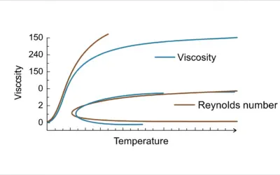
3. If the water temperature increases, what happens?
- The maximum suction head decreases.
- The maximum suction head increases.
- It has no effect on the suction head.
4. The NPSH Required (NPSHr) depends on:
- The pump's design (a manufacturer specification).
- The atmospheric pressure.
5. Increasing the suction pipe diameter (at a constant flow rate) will:
- Decrease the NPSH available.
- Have no effect on the NPSH available.
- Increase the NPSH available.
- Cavitation
- The phenomenon of a liquid boiling due to a local pressure drop, creating vapor bubbles that violently implode when they reach a higher pressure zone, causing noise, vibration, and material erosion.
- NPSH (Net Positive Suction Head)
- A measure of the pressure margin at a pump's inlet to prevent cavitation. NPSHa (Available) is a system property; NPSHr (Required) is a pump property.
- Vapor Pressure (\(P_v\))
- The pressure at which a liquid will boil at a given temperature. It increases sharply with temperature.
- Head Loss (\(\Delta H_T\))
- Energy (expressed in feet of fluid) lost by a moving fluid, primarily due to friction against pipe walls and turbulence from fittings.

0 Comments