Sizing a Pump for a Hydraulic Press
Context: Sizing a Hydraulic Power Unit (HPU)The component assembly that converts primary energy (usually electric or diesel) into hydraulic power. It consists of a motor, a pump, and a reservoir..
This exercise will guide you through the fundamental calculations required to size a hydraulic pump for a specific application. We will be designing a system for a simple hydraulic press. This process involves determining the required pressure, flow rate, and power, which are the three pillars of fluid power system design. We will use standard US customary units (PSI, GPM, inches).
Pedagogical Note: This exercise teaches you to translate mechanical requirements (force and speed) into hydraulic requirements (pressure and flow). This is the most critical skill for designing or analyzing any fluid power circuit.
Learning Objectives
- Calculate the required system pressure based on force and area.
- Calculate the required pump flow rate based on cylinder volume and cycle time.
- Determine the Hydraulic Horsepower (HP)The amount of power being transferred by the fluid. Calculated as (Pressure x Flow) / 1714. needed for the application.
- Calculate the required pump displacement based on motor speed.
- Determine the input torque required from the prime mover (motor).
Study Data
Technical Specs
| Component | Specification |
|---|---|
| Actuator | Double-Acting Hydraulic Cylinder |
| Prime Mover | Standard NEMA Electric Motor |
| System Type | Open-Center, Fixed Displacement Pump |
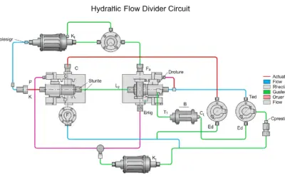
System Schematic
| Parameter | Symbol | Value | Unit |
|---|---|---|---|
| Required Force | F | 50,000 | lbs |
| Cylinder Bore (Diameter) | D | 6 | in |
| Cylinder Stroke | L | 24 | in |
| Required Extension Time | t | 5 | s |
| Motor Speed | N | 1750 | RPM |
Questions to Solve
- Calculate the required system pressure (in PSI) to achieve the desired force.
- Calculate the required flow rate (in GPM) to achieve the extension time.
- Calculate the required Hydraulic Horsepower (HP) for the system.
- Calculate the required pump displacement (in CIR) assuming 95% volumetric efficiency.
- Calculate the input torque (in in-lbs) needed to drive the pump, assuming 90% mechanical efficiency.
Fluid Power Fundamentals (US Units)
To solve this problem, we need a few key formulas specific to US customary units.
1. Pascal's Law (Pressure)
Pressure is defined as Force (F) distributed over an Area (A). This is the foundation of all hydraulics.
\[ P = \frac{F}{A} \]
Where P is in Pounds per Square Inch (PSI), F is in Pounds (lbs), and A is in Square Inches (in²). The area of the cylinder is \( A = \pi \cdot r^2 \) or \( A = \frac{\pi \cdot D^2}{4} \).
2. Flow, Displacement, and Power
These formulas use conversion factors to work with common units (GPM, PSI, HP, CIR).
- Flow Rate (GPM): \( Q = \frac{V}{t} \). To convert from in³/sec to GPM: \( Q_{\text{GPM}} = \frac{V_{\text{in}^3}}{t_{\text{sec}}} \times \frac{60 \text{ sec}}{1 \text{ min}} \times \frac{1 \text{ gal}}{231 \text{ in}^3} \)
- Pump Flow (GPM): \( Q_{\text{GPM}} = \frac{D_p \times N}{231} \times \eta_{\text{vol}} \)
- Hydraulic HP: \( HP = \frac{P \times Q}{1714} \)
Correction: Sizing a Pump for a Hydraulic Press
Question 1: Calculate the required system pressure (in PSI).
Principle
To find the pressure, we use Pascal's Law. We need to find the minimum pressure (in PSI) inside the cylinder that can generate the required 50,000 lbs of force over the area of the 6-inch diameter piston.
Mini-Lesson
The force generated by a cylinder is a direct product of the fluid pressure and the effective area it acts upon. We are pushing with the "cap end" (the full face) of the piston, so we use the full bore area. The formula is \( F = P \times A \). By rearranging it, we get \( P = F / A \).
Pedagogical Note
Think of this as a strategy: always find your Area (A) first. It's the foundation for many other calculations, including pressure and volume.
Standards
Calculations are based on standard ASME (American Society of Mechanical Engineers) principles for fluid dynamics. We are assuming an ideal system for this step.
Formule(s)
We will use two formulas: one for the area of the circle (piston face) and one for the pressure.
Piston Area
Pressure
Assumptions
We make a few assumptions for this basic calculation.
- The 50,000 lbs force is the only load; we neglect the weight of the platen.
- We neglect any frictional losses in the cylinder seals (typically 3-5%).
- Pressure is uniform across the entire piston face.
Data
These are the numbers from the problem statement that we need for this step.
| Parameter | Symbol | Value | Unit |
|---|---|---|---|
| Required ForceThe external load the hydraulic cylinder must overcome. | F | 50,000 | lbs |
| Cylinder BoreThe internal diameter of the cylinder body. | D | 6 | in |
Tips
A 6-inch bore cylinder is very common. Its area (\( \approx 28.27 \text{ in}^2 \)) is a good number to remember, as is a 4-inch bore (\( \approx 12.57 \text{ in}^2 \)).
Schema (Before Calculation)
This diagram shows the force (F) being applied to the piston area (A), which generates the pressure (P).
Piston Force Diagram
Calculation(s)
First, we calculate the area of the piston. Then, we use that area to find the pressure.
Step 1: Calculate Piston Area (A)
We apply the formula \( A = \frac{\pi \cdot D^2}{4} \), substituting our diameter (D = 6 in).
Step 2: Calculate Pressure (P)
Now we use Pascal's Law, \( P = F / A \), substituting our force (F = 50,000 lbs) and the area (A = 28.274 in²) we just found.
Schema (After Calculation)
This diagram visualizes the resulting pressure. We would set a system relief valve (RV) just above this value, e.g., at 2000 PSI, to protect the system.
Pressure Result
Reflections
A required pressure of 1769 PSI is a very reasonable value for a hydraulic press. Most standard components (pumps, valves, hoses) are rated for 3000 PSI or more. This gives us confidence in our design. We would likely set the system's relief valve slightly higher, perhaps at 2000 PSI.
Key Watch-Outs
Don't forget to square the diameter! A common mistake is to calculate \( (\pi \cdot D / 4) \) or \( (2 \cdot \pi \cdot r) \). The area formula is \( \pi \cdot r^2 \) or \( \frac{\pi \cdot D^2}{4} \). Forgetting this will make all subsequent calculations incorrect.
Key Takeaways
- Pressure is always a result of resistance to flow. In this case, the 50,000 lb load is the resistance.
- The formula \( P = F / A \) is the most important relationship in hydraulics.
Did You Know?
Blaise Pascal (1623-1662), for whom the SI unit of pressure (Pa) is named, developed his principle on fluid pressure. Despite this, PSI (Pounds per Square Inch) remains the dominant unit in US industry.
FAQ
Frequently asked questions for this step.
Final Result
Your Turn
Using the same cylinder (A = 28.274 in²), what pressure would be required to generate a force of 60,000 lbs?
Summary Card
Summary (Q1):
- Concept: Pascal's Law
- Formulas: \( A = \frac{\pi \cdot D^2}{4} \), \( P = F / A \)
- Result: Pressure = 1769 PSI
Question 2: Calculate the required flow rate (in GPM).
Principle
Flow rate is the "speed" of the hydraulic system. We need to move the cylinder (volume) a certain distance (stroke) in a specific amount of time. We must calculate the total volume of the cylinder and then determine how fast we need to fill it (in Gallons Per Minute) to meet the 5-second time requirement.
Mini-Lesson
Flow rate is the 'speed' of an actuator. A pump does not *create* pressure; it *creates* flow. Pressure is only created when this flow meets resistance (like the 50,000 lb load). The relationship is: \( \text{Speed} = \text{Flow} / \text{Area} \).
Pedagogical Note
Always calculate the total volume (in³) first. Once you have that, converting to GPM is just a unit conversion. Don't try to do it all in one step, as it's easy to make a mistake with the factors of 60 and 231.
Standards
The US Gallon (used in GPM) is legally defined as 231 cubic inches. This is a fixed standard and is different from the Imperial Gallon used in the UK.
Formule(s)
We first find the total volume of the cylinder, then convert that volume and time into the standard unit of Gallons Per Minute (GPM).
Cylinder Volume (in³)
Flow Rate (GPM)
Assumptions
We assume the 5 seconds is the *only* requirement. We are not accounting for acceleration/deceleration, or the time it takes for valves to shift.
- The pump provides constant flow instantly.
Data
We use the area from Q1 and the stroke/time data from the problem statement.
| Parameter | Symbol | Value | Unit |
|---|---|---|---|
| Piston Area (from Q1) | A | 28.274 | in² |
| Cylinder Stroke | L | 24 | in |
| Extension Time | t | 5 | s |
| Conversion Factor | - | 231 | in³/gal |
Tips
The number 231 is a "magic number" in US fluid power. It's the number of cubic inches in one US Gallon. You will see it everywhere. Memorize it!
Schema (Before Calculation)
We need to fill this entire volume (V) in 5 seconds.
Cylinder Volume
Calculation(s)
First, find the volume in cubic inches. Then, convert to GPM.
Step 1: Calculate Cylinder Volume (V)
We find the total volume (V) by multiplying the area (A) by the stroke length (L).
Step 2: Calculate Flow Rate (Q) in GPM
We convert the volume (V) and time (t) to GPM. First, we find the flow in in³/sec, then multiply by the conversion factor (60 sec/min) / (231 in³/gal).
Schema (After Calculation)
The result is a required flow rate. This determines the size of the pump and also the size of the system's pipes and hoses, which must be large enough to handle 35.25 GPM without excessive friction.
Flow Requirement
Reflections
A flow rate of 35.25 GPM is a significant amount of oil. This tells us we are not dealing with a small hobbyist system; this is an industrial-grade machine. The pump, valves, and conductors (hoses/pipes) must all be sized to handle this flow without causing excessive heat or pressure drops.
Key Watch-Outs
Units, Units, Units! The biggest trap in this calculation is mixing up units. You have Volume (in³), Time (seconds), and the desired Output (Gallons per Minute). You MUST use the conversion factors (60 sec/min and 231 in³/gal) correctly. A good shortcut is the combined factor: \( \frac{60}{231} \approx 0.2597 \).
Key Takeaways
- Flow rate (GPM) dictates the speed of the actuator.
- The conversion factor 231 in³/gal is essential for US unit calculations.
Did You Know?
Handling 35 GPM requires large hoses! A common rule of thumb for a pressure line (like this one) is a fluid velocity of ~15 ft/sec. This would require a hose with an internal diameter of about 0.85 inches (a -16 or 1" hose).
FAQ
...
Final Result
Your Turn
Using the same cylinder (V = 678.58 in³), what flow rate (GPM) would be needed to extend in 4 seconds?
Summary Card
Summary (Q2):
- Concept: Flow rate is Volume divided by Time.
- Formulas: \( V = A \times L \), \( Q_{\text{GPM}} = \frac{V \times 60}{t \times 231} \)
- Result: Flow Rate = 35.25 GPM
Question 3: Calculate the required Hydraulic Horsepower (HP).
Principle
Horsepower is a measure of power, or "work over time." In hydraulics, power is the product of Pressure (effort) and Flow (speed). We now have both of these values. We can use a standard US-unit formula to combine them into a single "Hydraulic Horsepower" (HP) value. This represents the power the fluid itself is transmitting.
Mini-Lesson
Power is the rate of doing work. In hydraulics, this is the combination of *effort* (Pressure) and *speed* (Flow). You can have a high-pressure, low-flow system and a low-pressure, high-flow system that both require the same horsepower!
Pedagogical Note
The constant 1714 is your best friend for US-unit HP calculations. It simply combines all the conversions: \( \frac{231 \text{ in}^3/\text{gal}}{1} \times \frac{1 \text{ ft}}{12 \text{ in}} \times \frac{1 \text{ HP}}{33000 \text{ ft-lb/min}} \approx \frac{1}{1714} \).
Standards
The formula \( HP = (P \times Q) / 1714 \) is a standard in American fluid power engineering. The "1714" is a "magic number" that combines all the conversion factors (from GPM to in³/min, from PSI to lbs/in², from in-lbs/min to HP) into one convenient constant.
Formule(s)
There is only one main formula for this step.
Hydraulic Horsepower
Assumptions
This calculation gives the *Hydraulic* HP (the power of the fluid). It does not account for any inefficiencies. We assume the P and Q values are what is required *at the actuator*.
Data
We use our answers from the two previous questions.
| Parameter | Symbol | Value | Unit |
|---|---|---|---|
| Pressure (from Q1) | P | 1769 | PSI |
| Flow Rate (from Q2) | Q | 35.25 | GPM |
| Conversion Factor | - | 1714 | - |
Tips
A quick mental check: \( (\text{PSI} \times \text{GPM}) / 2000 \) is often close enough for a rough estimate. In our case: \( (1769 \times 35.25) / 2000 \approx 31 \text{ HP} \). This is in the ballpark of 36 HP and tells us our answer is reasonable.
Schema (Before Calculation)
Pressure and Flow are the two inputs that produce Power.
Power Calculation
Calculation(s)
This is a direct application of the formula using our results from Q1 and Q2.
Step 1: Calculate Hydraulic Horsepower (HP)
We substitute our calculated pressure (P = 1769 PSI) and flow rate (Q = 35.25 GPM) into the HP formula.
This means the fluid itself is transmitting 36.38 horsepower. The input motor must be stronger to account for inefficiencies.
Schema (After Calculation)
The result (36.38 HP) is the *output* power. The *input* power from the motor must be higher to account for efficiency losses (heat, friction).
Power Flow
Reflections
This 36.38 HP is the power the *fluid* must deliver. The *input* power from the electric motor must be higher to overcome pump inefficiencies. For example, if the pump is 85% efficient, the motor will need to be at least \( 36.38 / 0.85 = 42.8 \text{ HP} \). We would select the next standard motor size, which would be 50 HP.
Key Watch-Outs
HP vs. Input HP: Do not confuse Hydraulic HP (the output) with Input HP (the motor size). Hydraulic HP is what the fluid does; Input HP is what the motor provides. They are related by efficiency: \( HP_{\text{in}} = HP_{\text{out}} / \eta_{\text{total}} \).
Key Takeaways
- Hydraulic Power (HP) is the product of Pressure and Flow.
- The constant 1714 is used to calculate HP from PSI and GPM.
Did You Know?
One horsepower (1 HP) was defined by James Watt in the 18th century as the power needed to lift 33,000 pounds by one foot in one minute. This was based on the work an average "mill horse" could do.
FAQ
...
Final Result
Your Turn
If the pump has an overall efficiency of 85% (\( \eta = 0.85 \)), what is the required Input HP (motor size) for this system? (Hint: \( HP_{\text{in}} = HP_{\text{out}} / \eta \))
Summary Card
Summary (Q3):
- Concept: Hydraulic Power is Pressure x Flow.
- Formula: \( HP = (P \times Q) / 1714 \)
- Result: Hydraulic HP = 36.38 HP
Question 4: Calculate the pump displacement (in CIR).
Principle
Now we select the physical pump. A pump's size is defined by its "Displacement," the volume of fluid it moves in one single revolution. This is usually measured in Cubic Inches per Revolution (CIR)The volume of liquid a pump moves during one full rotation of its shaft.. We know the total flow we need (35.25 GPM) and the speed of the motor (1750 RPM). We can now find the displacement that connects them.
Mini-Lesson
A pump's theoretical flow is its displacement (CIR) times its speed (RPM). This gives a result in cubic inches per minute. We must divide by 231 (in³/gal) to get GPM. \( Q_{\text{GPM}} = \frac{D_p \times N}{231} \). However, no pump is perfect; some fluid "slips" back, an inefficiency called volumetric efficiency (\(\eta_{\text{vol}}\))The ratio of actual flow delivered by a pump to the theoretical flow it should deliver. Usually 90-98%.. The *actual* flow is \( Q = \frac{D_p \times N}{231} \times \eta_{\text{vol}} \). We must rearrange this to solve for \( D_p \).
Pedagogical Note
This step connects the 'hydraulic' side (GPM) to the 'mechanical' side (RPM). The displacement \( D_p \) is the 'gear ratio' that links them. Notice how efficiency is in the denominator: you need a *larger* pump to make up for the flow that slips by.
Standards
Pump displacement (CIR or cm³/rev) is the primary specification in all manufacturer catalogs (like Bosch Rexroth, Parker, Eaton). Volumetric efficiency (\(\eta_{\text{vol}}\)) is a tested value, also provided by the manufacturer, which often varies with pressure and speed.
Formule(s)
We rearrange the pump flow formula to solve for Displacement (\( D_p \)).
Pump Displacement (CIR)
Assumptions
We assume a constant 95% volumetric efficiency. In reality, this efficiency drops as system pressure increases (more internal leakage).
- Motor speed is constant at 1750 RPM under load.
Data
We use our flow rate, the given motor speed, and a typical efficiency.
| Parameter | Symbol | Value | Unit |
|---|---|---|---|
| Flow Rate (from Q2) | Q | 35.25 | GPM |
| Motor Speed | N | 1750 | RPM |
| Volumetric Efficiency | \(\eta_{\text{vol}}\) | 0.95 | (95%) |
| Conversion Factor | - | 231 | in³/gal |
Tips
The formula can be simplified: \( D_p \approx (Q \times 243) / N \) if you assume a typical 95% efficiency (\( 231 / 0.95 \approx 243 \)). Try it: \( (35.25 \times 243) / 1750 \approx 4.90 \text{ CIR} \). It's a great shortcut.
Schema (Before Calculation)
We know the speed (RPM) and the desired output (GPM). We need to find the size of the pump (CIR) that connects them.
Finding Pump Displacement
Calculation(s)
We plug our values into the rearranged formula.
Step 1: Calculate Displacement (D_p)
We rearrange the pump flow formula to solve for Displacement (\(D_p\)). We use our target flow rate (Q), the motor speed (N), and the given volumetric efficiency (\(\eta_{\text{vol}}\)).
Schema (After Calculation)
The result is a physical pump size. We would now go to a catalog and find a pump with a displacement of 4.90 CIR or slightly larger.
Pump Selection
Reflections
The required displacement is 4.90 CIR. Pumps are sold in standard sizes. We would look at a manufacturer's catalog and select the next *available* size up, which might be a 5.0 CIR or 5.25 CIR pump. Choosing a slightly larger pump is standard practice, as it ensures we meet our flow requirement, and any excess flow is simply returned to the tank via the relief valve.
Key Watch-Outs
Efficiency placement! Volumetric efficiency (\(\eta_{\text{vol}}\)) goes with flow (\(Q, N, D_p\)). Mechanical efficiency (\(\eta_{\text{mech}}\)) goes with torque and power. Don't mix them up. Flow (GPM) is *lost*, so you need a bigger pump (divide by \(\eta_{\text{vol}}\)).
Key Takeaways
- Pump size (CIR) is the link between motor speed (RPM) and fluid flow (GPM).
- You must account for volumetric efficiency, or your system will be too slow.
Did You Know?
Common pump types include gear pumps (simple, robust), vane pumps (quieter, variable), and piston pumps (high pressure, high efficiency, and most expensive). This 4.90 CIR pump would likely be a gear or piston pump.
FAQ
...
Final Result
Your Turn
What displacement (CIR) would be required if we used a slower (and cheaper) 1150 RPM motor? (Use \( \eta_{\text{vol}} = 0.95 \))
Summary Card
Summary (Q4):
- Concept: Pump displacement links RPM to GPM.
- Formula: \( D_p = (Q \times 231) / (N \times \eta_{\text{vol}}) \)
- Result: Displacement = 4.90 CIR
Question 5: Calculate the input torque (in in-lbs).
Principle
Torque is the "twisting force" required to turn the pump's shaft. The electric motor must supply at least this much torque. Torque is a function of the pressure (P) the pump must overcome, its displacement (D), and its mechanical efficiency (\(\eta_{\text{mech}}\))The ratio of power delivered by the fluid to the power put into the pump shaft. Accounts for friction..
Mini-Lesson
Torque is to rotation what Force is to linear motion. The pump requires torque to push the fluid against the pressure. \( \text{Torque} \approx \text{Pressure} \times \text{Displacement} \). We divide by \( 2\pi \) to average this force over a full rotation, and divide by efficiency (\(\eta_{\text{mech}}\)) because the motor must also overcome friction.
Pedagogical Note
This calculation is the 'force' side of the equation. Q4 was the 'speed' side. Just like \( \text{Power} = \text{Force} \times \text{Speed} \), \( \text{Power} = \text{Torque} \times \text{Rotational Speed (RPM)} \). The 'Tips' section shows this exact check.
Standards
Torque is almost always specified in in-lbs or ft-lbs in the US. Electric motor specifications will always list a "Full Load Torque" (FLT) rating, which must be *greater* than the torque you calculate here.
Formule(s)
The theoretical torque is the pressure multiplied by the displacement, divided by \( 2\pi \) (to convert from a linear force to a rotational one). We must then divide by the mechanical efficiency to find the *actual* input torque needed.
Input Torque (in-lbs)
Assumptions
We assume a constant 90% mechanical efficiency. This accounts for all friction in the pump's bearings, gears, and seals.
- The pressure is a constant 1769 PSI.
Data
We use our calculated pressure and displacement, and a standard efficiency value.
| Parameter | Symbol | Value | Unit |
|---|---|---|---|
| Pressure (from Q1) | P | 1769 | PSI (lbs/in²) |
| Displacement (from Q4) | \(D_p\) | 4.90 | CIR (in³/rev) |
| Mechanical Efficiency | \(\eta_{\text{mech}}\) | 0.90 | (90%) |
Tips
You can also find torque from horsepower and RPM using the formula: \( T_{\text{in-lbs}} = \frac{HP_{\text{in}} \times 63025}{N} \). Using our 42.8 Input HP from Q3: \( T = (42.8 \times 63025) / 1750 \approx 1542 \text{ in-lbs} \). This is a great way to double-check your answer! (The small difference is due to rounding in the efficiency values).
Schema (Before Calculation)
The motor provides torque to turn the pump shaft. The pump converts this into fluid pressure.
Torque Input
Calculation(s)
We apply the direct torque formula.
Step 1: Calculate Input Torque (T)
We use the formula for torque, substituting our pressure (P), displacement (\(D_p\)), and the given mechanical efficiency (\(\eta_{\text{mech}}\)).
Schema (After Calculation)
The motor must supply 1533 in-lbs of torque. A standard 50 HP / 1750 RPM motor supplies ~1780 in-lbs, so our design is safe.
Torque Check
Reflections
The motor must be able to provide 1533 in-lbs of torque at 1750 RPM. This confirms our selection of a 50 HP motor (a standard 50 HP, 1750 RPM motor provides about 1780 in-lbs of torque, which is greater than our 1533 in-lbs requirement). Our design is consistent.
Key Watch-Outs
Mechanical vs. Volumetric Efficiency: Do not use \(\eta_{\text{vol}}\) here! This calculation is about *torque and friction*, which is \(\eta_{\text{mech}}\). Also, the \( 2\pi \) is essential. Forgetting it will give a result that is \( \approx 6.28 \) times too large.
Key Takeaways
- Torque is a function of Pressure and Displacement.
- The motor must be sized for both HP *and* Torque requirements.
Did You Know?
The total (or 'overall') efficiency of the pump is \(\eta_{\text{total}} = \eta_{\text{vol}} \times \eta_{\text{mech}}\). In our case, that is \( 0.95 \times 0.90 = 0.855 \) (or 85.5%). This matches the 85% efficiency we used in the HP calculation check!
FAQ
...
Final Result
Your Turn
What would the torque be if the pump was less efficient, with a mechanical efficiency of only 85% (\( \eta_{\text{mech}} = 0.85 \))?
Summary Card
Summary (Q5):
- Concept: Torque is the rotational force needed to turn the pump.
- Formula: \( T = (P \times D_p) / (2\pi \times \eta_{\text{mech}}) \)
- Result: Torque = 1533 in-lbs
Interactive Tool: Power Simulator
Use the sliders to see how changing Pressure and Flow Rate affects the required Hydraulic and Input (Motor) Horsepower. This tool uses the formulas from Step 3.
Input Parameters
Key Results
Final Quiz: Test Your Knowledge
1. What is the standard formula for Hydraulic Horsepower in US units?
2. A hydraulic cylinder has a 4-inch bore. What is its piston area?
3. In US fluid power, "GPM" is the standard abbreviation for:
4. If system pressure (P) increases, but flow rate (Q) stays the same, what happens to the required horsepower?
5. A pump has a displacement of 2.0 CIR. At 1800 RPM, what is its theoretical flow? (\( Q = (D \times N) / 231 \))
Glossary
- Pressure (PSI)
- Pounds per Square Inch. The unit of force intensity in the US system. It is the result of resistance to flow.
- Flow Rate (GPM)
- Gallons Per Minute. The standard US unit for measuring the volume of fluid moving through a system over time.
- Hydraulic Horsepower (HP)
- The power transmitted by the hydraulic fluid. This is the "output" power of the pump. 1 HP = 33,000 ft-lbs per minute.
- Displacement (CIR)
- Cubic Inches per Revolution. The volume of fluid a pump or motor moves in one single rotation. This defines the pump's "size".
- Pascal's Law
- A law stating that pressure applied to an enclosed fluid is transmitted undiminished to every portion of the fluid and the walls of the containing vessel. (P = F / A)
- Efficiency (\(\eta\))
- The ratio of power out to power in. Volumetric efficiency (\(\eta_{\text{vol}}\)) accounts for fluid leakage, while mechanical efficiency (\(\eta_{\text{mech}}\)) accounts for friction.

0 Comments