Calculating Singular Head Loss for a Valve
Context: Singular Head LossLocalized energy losses in a hydraulic circuit, caused by pipe fittings (elbows, valves, tees, etc.) that disrupt the fluid flow..
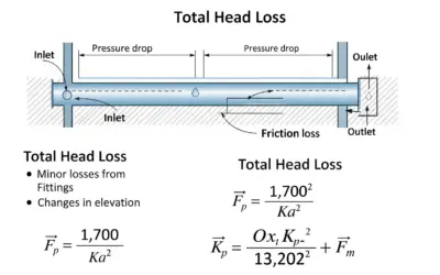
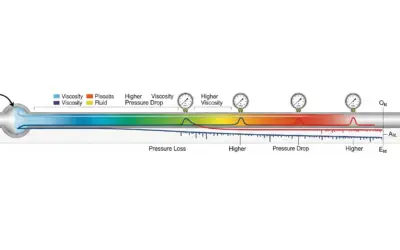
In any hydraulic circuit, the movement of a fluid is accompanied by an energy loss, known as "head loss". We distinguish between linear head loss (due to friction along pipes) and singular head loss, which occurs locally at obstructions. This exercise focuses on calculating the head loss caused by a valve, a critical component for flow regulation.
Pedagogical Note: This exercise will teach you how to quantify the impact of a control device on flow. This is a fundamental skill for correctly sizing pumps and designing efficient hydraulic networks.
Learning Objectives
- Understand and define the concept of singular head loss.
- Know how to determine the loss coefficient (K) for a valve.
- Apply the Darcy-Weisbach equation to calculate singular head loss.
- Analyze the influence of a valve's degree of opening on dissipated energy.
Study Data
Technical Data
| Characteristic | Value |
|---|---|
| Installation Type | Industrial cooling circuit |
| Fluid | Water at 68°F (20°C) |
| Valve Type | Gate Valve |
Chart: Loss Coefficient (K) for a Gate Valve
| Degree of Opening (%) | K Coefficient (dimensionless) |
|---|---|
| 100% (Open) | 0.2 |
| 75% | 1.5 |
| 50% | 4.0 |
| 25% | 20.0 |
Installation Diagram
| Parameter | Description or Formula | Value | Unit |
|---|---|---|---|
| Pipe Diameter | \( D \) | 4.0 | in |
| Flow Velocity | \( V \) | 6.5 | ft/s |
| Specific Weight of Water | \( \gamma = \rho \cdot g \) | 62.3 | lb/ft³ |
| Acceleration of Gravity | \( g \) | 32.2 | ft/s² |
Questions to Solve
- Assuming the gate valve is 50% open (half-open). Determine its head loss coefficient (K) using the data provided.
- Calculate the singular head loss (\( \Delta H \)) generated by the valve, expressed in feet (ft).
- Deduce the corresponding pressure drop (\( \Delta P \)) in **psi** (pounds per square inch).
- If the valve were fully open, the K coefficient would be 0.2. What would the new head loss be? Compare the results and conclude.
The Basics of Singular Head Loss
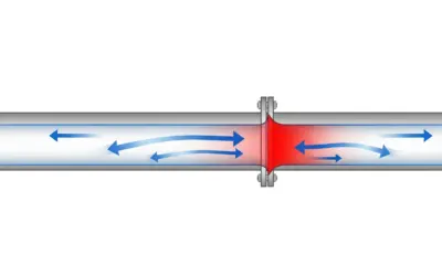
When a fluid passes through a component such as an elbow, tee, reducer, or valve, the local geometry disrupts the streamlines, creating turbulence and vortices that dissipate energy. This localized energy loss is called singular head loss.
1. Singular Head Loss Formula (Darcy-Weisbach)
Singular head loss, \( \Delta H \), is calculated using the following formula, where the kinetic energy of the fluid is multiplied by a dimensionless coefficient K:
\[ \Delta H = K \cdot \frac{V^2}{2g} \]
Where:
- \( \Delta H \): Singular head loss (in feet of fluid column)
- \( K \): Loss coefficient (dimensionless)
- \( V \): Average flow velocity in the pipe (in \( \text{ft/s} \))
- \( g \): Acceleration of gravity (in \( \text{ft/s²} \))
2. The Loss Coefficient (K)
The K coefficient is an empirical value that depends solely on the geometry of the singularity. The more the obstacle disrupts the flow, the higher the K value. For valves, K strongly depends on their type (gate, butterfly, ball...) and their degree of opening. These values are determined experimentally and are available in charts and hydraulic manuals.
Solution: Calculating Singular Head Loss for a Valve
Question 1: Determining the Loss Coefficient (K)
Principle
The K coefficient is a dimensionless number used to quantify the resistance an obstacle (here, the valve) poses to fluid flow. It can be seen as an "energy loss multiplier".
The head loss formula (\(\Delta H = K \cdot \frac{V^2}{2g}\)) compares the energy loss (\(\Delta H\)) to the fluid's kinetic energy (\(\frac{V^2}{2g}\)).
This K coefficient is not calculated theoretically (except in very simple cases); it is determined experimentally. Engineers have tested different types of valves, elbows, etc., in labs and measured the head loss to compile these "charts" (tables of values).
Given Data
The problem asks us to find the K coefficient for the gate valve when it is 50% open.
Procedure (Reading the Chart)
The procedure is to find the correct information in the chart. Below is an interactive version of this chart. Click on the row that you think is correct (corresponding to 50% opening).
| Degree of Opening (%) | K Coefficient (dimensionless) |
|---|---|
| 100% (Open) | 0.2 |
| 75% | 1.5 |
| 50% | 4.0 |
| 25% | 20.0 |
By clicking on the "50%" row, you see that the corresponding value is 4.0.
In-depth Chart Analysis
Understanding the Chart: Look at the evolution of the K values. They are not linear (they do not increase at a constant rate).
- 100% Open (K=0.2): The flow is almost unrestricted. The gate is retracted, but the valve body itself creates a very slight disturbance (turbulence), hence a very low, but non-zero, K value.
- 50% Open (K=4.0): The gate blocks half of the passage. The fluid must accelerate sharply to pass through the narrowed section, then it "expands" on the other side, creating significant vortices (eddies). It is these vortices that "break" the flow's energy and dissipate it as heat. A loss of 4 times the kinetic energy is already very significant.
- 25% Open (K=20.0): The effect is extreme. The passage is tiny, the velocity of the fluid "jet" is very high, and the downstream turbulence zone is massive. The flow is completely disrupted. K=20 represents a colossal energy loss, which is why a valve is so effective at "killing" flow.
Non-linearity: Going from 100% to 75% adds 1.3 to K (1.5 - 0.2). But going from 50% to 25% adds 16.0 to K (20.0 - 4.0). The resistance increases almost exponentially as the valve closes.
Points of Caution
Be careful not to confuse the K coefficients for different types of valves (an elbow, a butterfly valve...) or for the wrong degree of opening. Reading the chart must be precise.
Final Result
Your Turn
Using the same chart, what would the K coefficient be if the valve was 75% open?
Question 2: Calculating the Singular Head Loss (\( \Delta H \))
Principle
We apply the Darcy-Weisbach equation for singular head loss, using the K coefficient and the flow's kinetic energy (\( V^2/2g \)). This formula reflects that the energy dissipated is proportional to the fluid's kinetic (motion) energy.
Mini-Lesson
The term \( \frac{V^2}{2g} \) is called the "dynamic head". It represents the kinetic energy of the fluid per unit weight and is expressed in feet. It is a measure of motion energy. The formula \( \Delta H = K \cdot \frac{V^2}{2g} \) therefore means that the head loss is K times the dynamic head.
Pedagogical Note
The most common mistake here is forgetting to square the velocity. Always remember that kinetic energy depends on the square of the velocity, so the head loss, which is a dissipation of this energy, also depends on it.
Standards
The Darcy-Weisbach equation is universally accepted and forms the basis of all head loss calculations in hydraulics, including in US engineering practice.
Formula(s)
Singular Head Loss Formula
Assumptions
We assume that V is the average velocity in the pipe section and that the flow is incompressible, which is an excellent approximation for water under these conditions.
Given Data
We use the values from the problem statement and Question 1.
| Parameter | Symbol | Value | Unit |
|---|---|---|---|
| Loss Coefficient | K | 4.0 | - |
| Flow Velocity | V | 6.5 | ft/s |
| Acceleration of Gravity | g | 32.2 | ft/s² |
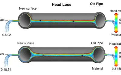
Diagram (Before Calculation)
Head Loss Visualization
Calculation(s)
We apply the formulas seen earlier. Let's detail the substitution of values:
We start by writing the full formula, replacing each variable with its numerical value from the problem.
Applying the Formula (Substitution)
This block shows the complete equation with K=4.0, V=6.5 ft/s, and g=32.2 ft/s².
Step-by-Step Calculation
To simplify the calculation, we first isolate the term \( \frac{V^2}{2g} \), which represents the fluid's kinetic energy (or 'dynamic head').
1. First, calculate the dynamic head (kinetic energy):
We get a dynamic head of about 0.656 feet. This is the energy that will be 'lost' 4 times over (because K=4.0).
Now, we take this result (the dynamic head) and multiply it by our loss coefficient K.
2. Next, multiply by the K coefficient:
The calculation confirms the head loss is 2.624 ft.
Reflections
A head loss of 2.624 ft means the valve dissipates as much energy as if the fluid had to be lifted 2.62 feet. This energy, supplied by the pump, is converted into heat and noise.
Points of Caution
Ensure all your units are consistent (US Customary): velocity in ft/s, g in ft/s². The result \( \Delta H \) will then be in feet.
Key Takeaways
Singular head loss is the product of a geometric coefficient (K) and the fluid's dynamic head (\(V^2/2g\)).
Did you know?
In advanced numerical simulations (CFD), a simple K coefficient isn't used. The software directly simulates the vortices and recirculation zones to calculate energy dissipation with high precision, but this requires significant computing power.
FAQ
It's normal to have questions.
Final Result
Your Turn
If the fluid velocity increased to 8 ft/s (still with K=4.0), what would the new head loss be in ft?
Question 3: Calculating the Pressure Drop (\( \Delta P \))
Principle
The head loss (\( \Delta H \)), expressed in feet of fluid, can be converted into a pressure drop (\( \Delta P \)) using the fundamental principle of hydrostatics. The pressure exerted by a column of fluid is its specific weight times its height.
Mini-Lesson
The relationship \( \Delta P = \gamma \cdot \Delta H \) (where \( \gamma = \rho g \)) is the key. \( \gamma \) (gamma) is the "specific weight" of the fluid.
- \( \Delta P \) will be in pounds per square foot (psf).
- \( \gamma \) is in lb/ft³.
- \( \Delta H \) is in ft.
To get the final answer in pounds per square inch (psi), we must divide the result in psf by 144 (since 1 ft² = 144 in²).
Pedagogical Note
Think of \( \Delta H \) (in feet) as the energetic "cause" and \( \Delta P \) (in psi) as the measurable "consequence" you would read on a pressure gauge.
Standards
The standard unit for pressure in US engineering is psi (pounds per square inch). Calculations often yield psf (pounds per square foot), which must be converted.
Formula(s)
Hydrostatic Pressure Formula
Assumptions
We use the standard specific weight of water at 68°F, \( \gamma \approx 62.3 \text{ lb/ft³} \).
Given Data
| Parameter | Symbol | Value | Unit |
|---|---|---|---|
| Specific Weight of Water | \(\gamma\) | 62.3 | lb/ft³ |
| Singular Head Loss | \(\Delta H\) | 2.624 | ft |
Tips
A handy shortcut: 1 psi $\approx$ 2.31 ft of water head. So, \( 2.624 \text{ ft} / 2.31 \text{ ft/psi} \approx 1.14 \text{ psi} \). This is a great way to check your answer's order of magnitude.
Diagram (Before Calculation)
Measuring Pressure Drop
Calculation(s)
We will first calculate the pressure drop in pounds per square foot (psf), then convert to psi.
Calculating pressure drop in psf (lb/ft²)
The calculation gives us 163.48 pounds per square foot (psf).
Now, we convert psf to psi by dividing by 144 (since 1 ft² = 144 in²).
Conversion to psi (lb/in²)
This pressure drop is approximately 1.14 psi.
Reflections
A pressure drop of 1.14 psi may seem small, but in a large network with many fittings, these losses add up and can require a significant increase in pump power.
Points of Caution
The most common error is forgetting to convert from psf to psi. Pressure gauges read in psi, so this final conversion is critical.
Key Takeaways
The conversion between head loss in feet (\(\Delta H\)) and pressure drop in psi (\(\Delta P\)) is \(\Delta P_{\text{psi}} = (\gamma \cdot \Delta H) / 144\).
Did you know?
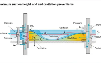
Standard atmospheric pressure at sea level is about 14.7 psi. This corresponds to the pressure exerted by a column of water about 33.9 feet high! This is what limits the maximum suction height of a pump.
FAQ
It's normal to have questions.
Final Result
Your Turn
If the head loss was 5 ft in an oil circuit (Specific Gravity = 0.85), what would the pressure drop be in **psi**?
Question 4: Comparison with the Valve Fully Open
Principle
A fully open valve disrupts the flow much less. Its K coefficient is therefore significantly lower. We will recalculate the head loss with this new value to quantify the energy savings.
Mini-Lesson
Even when fully open, a gate valve still presents a slight obstacle to the flow (the gate's thickness, the guides, etc.). This is why its K coefficient is not zero, but simply very low. Valves like "full-port" ball valves have even lower K values because, once open, they present almost no obstruction.
Pedagogical Note
This question is intended to make you aware of the order of magnitude. The purpose of a control valve is to be able to create significant head loss when needed, but it must create as little as possible when in the "fully open" position.
Formula(s)
New Head Loss Formula
Assumptions
We assume the flow velocity remains the same (6.5 ft/s). In reality, if the valve were opened, the total circuit resistance would decrease, and for the same pump, the flow rate (and thus velocity) would slightly increase.
Given Data
| Parameter | Symbol | Value | Unit |
|---|---|---|---|
| Coefficient (valve open) | K' | 0.2 | - |
| Flow Velocity | V | 6.5 | ft/s |
Tips
Since the dynamic head was already calculated in Question 2 (0.656 ft), there's no need to redo the full calculation. We can simply multiply this value by the new K.
Calculation(s)
We redo the exact same calculation as in Question 2, but using the new coefficient K' = 0.2 (for the 100% open valve).
Calculating the new head loss
As we can see, the head loss is now 0.131 ft, a very low value, which is logical for a fully open valve.
Comparison
Loss (valve at 50%): \( \Delta H \approx 2.624 \text{ ft} \)
Loss (valve at 100%): \( \Delta H' \approx 0.131 \text{ ft} \)
To quantify the difference, we calculate the ratio between the head loss at 50% and the head loss at 100%.
This calculation shows that the head loss at 50% opening is 20 times greater than that of the open valve.
Conclusion: The head loss is 20 times lower when the valve is fully open compared to its 50% position. This clearly illustrates the valve's role: by closing, it creates a major obstruction that dissipates energy (creates head loss) to control the flow.
Points of Caution
Never assume an open valve has K = 0. This is a common mistake. Any component inserted in a line creates some loss, even if minimal.
Key Takeaways
A valve's primary function is to regulate (or stop) flow, which is done at the cost of intentionally created energy loss. The choice and adjustment of valves are therefore a crucial trade-off between process control needs and the hydraulic system's energy efficiency.
Did you know?
To improve energy efficiency, variable speed drives (VSDs) are increasingly used on pumps. Instead of "throttling" the circuit with a valve to reduce flow, it's preferable to slow down the pump. This adjusts the flow rate while significantly reducing electricity consumption, as power varies with the cube of the rotation speed.
FAQ
It's normal to have questions.
Final Result
Your Turn
A 90° elbow has a K of about 0.9. For the same 6.5 ft/s velocity, what head loss does it generate?
Interactive Tool: Head Loss Simulator
Use the sliders to see how flow velocity and the singularity's K coefficient influence head loss and pressure drop.
Input Parameters
Key Results
Final Quiz: Test Your Knowledge
1. What is the unit of the singular head loss coefficient K?
2. The singular head loss \( \Delta H \) is proportional to:
3. What is the cause of a singular head loss?
4. In the formula \( \Delta P = \gamma \cdot \Delta H \), what does the symbol \( \gamma \) represent?
5. How does a valve's K coefficient generally change as you decrease its opening percentage (i.e., close it more)?
- Singular Head Loss
- Localized energy loss, expressed in height of fluid column (ft) or in pressure (psi), due to a local geometric disruption of the flow (valve, elbow, tee, etc.).
- Loss Coefficient (K)
- A dimensionless number that quantifies the hydraulic resistance of a local obstacle. Its value is determined experimentally and depends on the shape of the obstacle.
- Gate Valve
- A type of valve where the sealing member is a plate (the gate) that moves perpendicular to the flow to block it. It is primarily designed for on/off service (fully open or fully closed).
- Specific Weight (Gamma, \( \gamma \))
- The weight per unit volume of a substance. For water, it is approximately 62.3 lb/ft³. It is related to density (\( \rho \)) by \( \gamma = \rho g \).

0 Comments