Flow Divider Circuit Design
Context: Hydraulic Power & Flow Division
In power hydraulics, it is often necessary to split the flow from a single pump to operate two or more separate actuators (like hydraulic cylinders or motors) simultaneously. A simple "Tee" fitting is unreliable because the oil will follow the path of least resistance, causing one actuator to move before the other. To solve this, we use a flow dividerA hydraulic valve that splits a single input flow into two or more output flows., which ensures that each circuit receives a specific, often equal, amount of flow, regardless of individual load pressures.
Pedagogical Note: This exercise will teach you how to analyze a basic flow divider circuit. You will calculate the pressure required from the pump, the power consumed by the system, and the overall efficiency, which are critical skills for designing any hydraulic system.
Learning Objectives
- Understand the function of a spool-type flow divider.
- Calculate actuator speed based on flow rate and cylinder dimensions.
- Apply Pascal's Law to determine pressure intensification.
- Calculate the required pump pressure and input hydraulic horsepower.
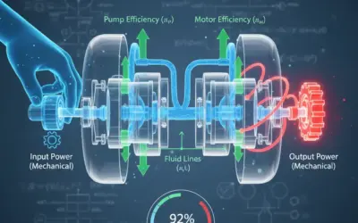
- Determine the overall efficiency of the flow divider circuit.
System Data
Technical Data
| Characteristic | Value |
|---|---|
| Pump Flow Rate (\(Q_p\)) | 20 GPM |
| Cylinder Bore Diameter (d) | 4.0 inches |
| Cylinder Rod Diameter | (Not relevant for extension) |
| Load on Cylinder A (\(F_A\)) | 15,000 lbs |
| Load on Cylinder B (\(F_B\)) | 10,000 lbs |
| Relief Valve Setting (RV) | 2500 psi |
Hydraulic Circuit Diagram
Questions
- Calculate the flow rate to each cylinder (in GPM).
- Calculate the piston area for the cylinders (in in²).
- Calculate the pressure required to move each load (\(P_A\) and \(P_B\)) (in psi).
- Determine the required pump pressure (\(P_{in}\)) and the total input horsepower (HP).
- Calculate the total output horsepower and the overall efficiency of the circuit.
Fundamentals of Power Hydraulics
To solve this problem, we will use fundamental principles of fluid power, specifically those related to flow, pressure, and power.
1. Flow Rate and Actuator Speed
The speed of an actuator (like a cylinder) is directly proportional to the flow rate it receives and inversely proportional to its area. The key conversion factor in US units is 231 in³ = 1 Gallon.
\[ \text{Speed (in/min)} = \frac{\text{Flow (GPM)} \times 231}{\text{Area (in}^2)} \]
2. Pressure, Force, and Area (Pascal's Law)
Pressure (\(P\)) is defined as Force (\(F\)) distributed over an Area (\(A\)). This is the most fundamental formula in hydraulics.
\[ P \text{ (psi)} = \frac{F \text{ (lbs)}}{A \text{ (in}^2)} \]
3. Hydraulic Horsepower
Power is the rate of doing work. In hydraulics, it's a function of both flow (\(Q\)) and pressure (\(P\)). The common constant used in US customary units is 1714.
\[ \text{Horsepower (HP)} = \frac{P \text{ (psi)} \times Q \text{ (GPM)}}{1714} \]
Solution: Flow Divider Circuit Design
Question 1: Calculate the flow rate to each cylinder (in GPM).
Principle
The problem states we are using a "50-50" flow divider. This means its primary function is to take the total input flow from the pump and split it equally between its two output ports (Port A and Port B), regardless of the pressure at those ports.
Mini-Course
A spool-type flow divider consists of two precision-matched spools mechanically linked together (or hydraulically linked by a fluid passage). If flow to one side (e.g., the high-pressure side) slows down, the spool assembly shifts, creating a restriction on the *other* side (the low-pressure side). This forces the flow to redirect to the high-pressure side, thus maintaining an equal split. For this problem, we assume it's a perfect 50-50 split.
Pedagogical Remark
Think of this like two revolving doors connected by a shaft. If one person tries to run through their door (low resistance) and another person has to push hard (high resistance), the connecting shaft forces both doors to turn at the same speed. The flow divider does the same thing with oil flow.
Norms
In industry, flow dividers are rated by their "split ratio" (e.g., 50/50, 60/40) and their "accuracy." No divider is perfect. A typical accuracy is around \(\pm 5\%\). For academic purposes, we will assume "ideal" performance, meaning the split is exactly 50/50.
Formula(s)
The formula is based on the split ratio. For a 50-50 divider:
This gives the flow rate at output A (\(Q_A\)) based on the pump flow (\(Q_p\)).
Similarly, this gives the flow rate at output B (\(Q_B\)).
Hypotheses
We must make the following assumptions to proceed:
- The flow divider is 100% accurate (a perfect 50/50 split).
- The pump provides a constant, non-pulsating flow of 20 GPM (i.e., its volumetric efficiency is 100%).
- There are no leaks in the system.
Data
We only need one piece of data from the problem statement for this question.
| Parameter | Symbol | Value | Unit |
|---|---|---|---|
| Pump Flow RateThe total volume of fluid that the pump delivers per unit of time. | \(Q_p\) | 20 | GPM |
Tips
This first step is often straightforward. Don't overthink it. The purpose of a 50-50 flow divider is in its name. The loads and pressures (15,000 lbs, 10,000 lbs) do not affect the flow split in an ideal divider. They will become important in later questions.
Schematic (Before Calculations)
We are focusing on the flow path from the pump (P) to the flow divider (FD) and out to the two circuits (A and B).
Flow Path Schematic
Calculation(s)
We will apply the 50% split ratio to the total pump flow.
Step 1: Calculate Flow A
The flow directed to Cylinder A is 10 GPM.
Step 2: Calculate Flow B
The flow directed to Cylinder B is also 10 GPM, as expected.
Schematic (After Calculations)
Now we can update our schematic with the calculated flow values.
Flow Path with Results
Reflections
This step confirms that the total 20 GPM from the pump is split into two 10 GPM streams. This equal flow is what forces the two cylinders to attempt to move at the same speed, even though their loads are different. This is the entire point of a flow divider.
Vigilance Points
A common mistake is to think the flow will split proportionally to the load. For example, since Load A is higher, students might think it gets less flow. This is what happens with a simple 'Tee' fitting, but it is the exact opposite of what a flow divider is designed to do. It forces the split to be equal.
Key Points to Remember
- A flow divider's split ratio (e.g., 50/50) determines the output flow rates based on the input flow.
- In an ideal flow divider, the load pressures (\(P_A\) and \(P_B\)) do not affect the flow split.
Did You Know?
Spool-type flow dividers are not the only option. There are also "flow dividers" made from two or more hydraulic motors connected to a common shaft. Because all motors are forced to turn at the same speed, their output flow rates are also synchronized. These are often used for very high-accuracy applications and are called "rotary gear dividers."
FAQ
Here are common questions about this step.
Final Result
Try It Yourself
What would the flow to Cylinder A be if the pump supplied 30 GPM and the divider was a 60/40 split (with 60% going to A)?
Memo Card
Question 1 Summary:
- Key Concept: Flow Divider Function.
- Formula: \(Q_{\text{out}} = Q_{\text{in}} \times \text{Split Ratio}\).
- Key Takeaway: Loads do not affect the flow split in an ideal divider.
Question 2: Calculate the piston area for the cylinders (in in²).
Principle
The problem states we are using cylinders with a "bore diameter" of 4.0 inches. The bore is the internal diameter of the cylinder. The piston area is the area of this circle, which is the surface that the hydraulic fluid pushes against to create force.
Mini-Course
The area of a circle is a fundamental geometric calculation. When working with hydraulic cylinders, we are almost always interested in the "bore area" (for extension) and the "annular area" (for retraction). Since the cylinders are extending to lift the load, we only need the full bore area. The rod diameter is irrelevant for this calculation, as the fluid pushes on the entire face of the piston.
Pedagogical Remark
This is a straightforward geometry problem. The only "trick" is to remember the formula for the area of a circle and to use the diameter correctly. Remember that the radius (\(r\)) is half the diameter (\(d\)).
Norms
In the US, cylinder bores are specified in inches. All standard calculations for area in hydraulics use square inches (in²). This pairs directly with pressure in pounds per square inch (psi) to give force in pounds (lbs), which is a very convenient system.
Formula(s)
The formula for the area of a circle (\(A\)) given its radius (\(r\)) is:
Since we are given the diameter (\(d\)), and we know \(r = d/2\), we can substitute this into the formula:
This second formula is often more direct as it allows us to use the diameter value from the problem statement.
Hypotheses
We assume the 4.0-inch bore diameter is precise and uniform.
Data
We only need one piece of data for this question.
| Parameter | Symbol | Value | Unit |
|---|---|---|---|
| Cylinder Bore DiameterThe internal diameter of the hydraulic cylinder body. | \(d\) | 4.0 | in |
Tips
A common mistake is to forget to square the radius, or to use the diameter directly in \(A = \pi \times d^2\). Always use \(A = \pi \times r^2\) or \(A = (\pi \times d^2) / 4\). For a 4-inch diameter, the radius is 2 inches. This is an easy number to work with.
Schematic (Before Calculations)
We are looking at a cross-section of the cylinder to identify the area the fluid acts upon.
Cylinder Piston Area
Calculation(s)
We will use the formula \(A = \pi \times r^2\). First, we find the radius \(r\).
Step 1: Calculate Radius
The radius of the piston is 2.0 inches.
Step 2: Calculate Area
The area of the piston face is approximately 12.57 square inches.
Schematic (After Calculations)
We can now label our schematic with the resulting area.
Cylinder Piston Area (Result)
Reflections
This area (\(A = 12.57 \text{ in}^2\)) is the "engine" of the actuator. It's the component that converts pressure (which we will find next) into usable force. A larger area would require less pressure to lift the same load, but it would also move slower for the same flow rate (as \(Speed \propto 1/A\)).
Vigilance Points
This calculation is for the extension stroke (the "cap end"). If the problem asked for the retraction speed or force, we would need the "annular area," which is the bore area minus the rod area. Since the rod diameter was not given, we know we are only interested in the extension stroke.
Key Points to Remember
- Actuator force is generated over the piston's bore area (\(A\)).
- The formula is \(A = \pi \times r^2\) or \(A = (\pi \times d^2) / 4\).
- This area is used for both force (\(F = P \times A\)) and speed (\(Speed = (Q \times 231) / A\)) calculations.
Did You Know?
The "rod area" can be significant. If this 4-inch bore cylinder had a 2-inch diameter rod, the retraction area would be \(A_{\text{annular}} = A_{\text{bore}} - A_{\text{rod}} = 12.57 \text{ in}^2 - (\pi \times 1^2) = 12.57 - 3.14 = 9.43 \text{ in}^2\). This is 25% less area, meaning it would retract 25% faster but could only pull with 75% of its pushing force (at the same pressure).
FAQ
Common questions for this step.
Final Result
Try It Yourself
What would the piston area be for a cylinder with a 5-inch bore diameter?
Memo Card
Question 2 Summary:
- Key Concept: Piston Area.
- Formula: \(A = \pi \times r^2 = (\pi \times d^2) / 4\).
- Key Takeaway: Use bore diameter for extension. \(A = \pi \times (2.0)^2 \approx 12.57 \text{ in}^2\).
Question 3: Calculate the pressure required to move each load (\(P_A\) and \(P_B\)) (in psi).
Principle
This is a direct application of Pascal's Law. We know the force (load) that each cylinder must overcome (\(F_A\) and \(F_B\)). We also know the area (\(A\)) over which that force is applied (which we calculated in Question 2). The pressure is simply the force divided by the area.
Mini-Course
Pressure (\(P\)) in a hydraulic system is not "created" by the pump; a pump creates *flow*. Pressure is created by *resistance* to that flow. In this case, the loads (\(F_A\) and \(F_B\)) are the resistances. The fluid pressure will rise to the exact level needed to overcome the load, and no higher. If the pump can't generate enough pressure, the load won't move.
Pedagogical Remark
This is where we see the two circuits behaving differently. Even though the flow to each cylinder is identical (10 GPM), the loads are different. This means the pressure required by each cylinder will also be different. Cylinder A has to work harder, so it will generate a higher back-pressure.
Norms
The standard unit for hydraulic pressure in the US is pounds per square inch (psi). Our inputs, force in pounds (lbs) and area in square inches (in²), are perfectly set up to give us a result in psi without any conversions.
Formula(s)
We will use the fundamental pressure formula, rearranged to solve for \(P\):
We will apply this formula twice: once for Cylinder A and once for Cylinder B.
Hypotheses
We make the following assumptions:
- The loads (\(F_A\) and \(F_B\)) are the only resistances. We are ignoring friction in the cylinder seals and in the pipes (for now).
- The loads are static and do not change as the cylinder moves.
Data
We need the loads from the problem statement and the area we just calculated.
| Parameter | Symbol | Value | Unit |
|---|---|---|---|
| Load on Cylinder AThe external force that Cylinder A must push against. | \(F_A\) | 15,000 | lbs |
| Load on Cylinder BThe external force that Cylinder B must push against. | \(F_B\) | 10,000 | lbs |
| Piston AreaThe calculated area of the piston face. | \(A\) | 12.57 | in² |
Tips
Check your units! Force *must* be in pounds (lbs) and area *must* be in square inches (in²) to get psi. Since they already are, this is a simple division problem. The most common error here is mixing up the loads or using the wrong area.
Schematic (Before Calculations)
This schematic shows the relationship between Force (F), Pressure (P), and Area (A) for each cylinder.
Force vs. Pressure Diagram
Calculation(s)
We apply the formula \(P = F/A\) to each cylinder.
Step 1: Calculate Pressure for Cylinder A (\(P_A\))
Cylinder A requires ~1193 psi to lift its 15,000 lb load.
Step 2: Calculate Pressure for Cylinder B (\(P_B\))
Cylinder B only requires ~796 psi to lift its 10,000 lb load.
Schematic (After Calculations)
We can now see the different pressure requirements.
Force vs. Pressure (Results)
Reflections
We now see the core of the problem. We have two parallel circuits being fed equal flow (10 GPM each), but they have different pressure requirements (1193 psi vs 796 psi). This pressure differential is the key to understanding the next step. How does the single pump provide two different pressures? It doesn't. The flow divider makes it possible.
Vigilance Points
Do not average the pressures. Do not add the pressures. These are two separate, parallel circuits. The pressure \(P_A\) is the pressure required in circuit A, and \(P_B\) is the pressure required in circuit B. They are independent of each other... for now.
Key Points to Remember
- Pressure is resistance. \(P = F/A\).
- Different loads on identical cylinders will result in different pressure requirements.
- Cylinder A needs 1193 psi. Cylinder B needs 796 psi.
Did You Know?
This phenomenon is why a simple 'Tee' fitting fails. If this circuit used a Tee, 100% of the 20 GPM flow would go to Cylinder B, because it only requires 796 psi to move. Cylinder B would extend fully, and only *after* it bottomed out (stalled) would the pressure rise high enough (to 1193 psi) to begin moving Cylinder A. They would not move simultaneously.
FAQ
Common questions for this step.
Final Result
Try It Yourself
What would the pressure in Cylinder A be if the load \(F_A\) was increased to 20,000 lbs?
Memo Card
Question 3 Summary:
- Key Concept: Pascal's Law.
- Formula: \(P = F / A\).
- Key Takeaway: \(P_A = 15000 / 12.57 \approx 1193 \text{ psi}\). \(P_B = 10000 / 12.57 \approx 796 \text{ psi}\).
Question 4: Determine the required pump pressure (\(P_{in}\)) and the total input horsepower (HP).
Principle
A spool-type flow divider works by establishing a single inlet pressure (\(P_{in}\)) that is high enough to power the most-loaded circuit. It then *throttles* the flow to the other, less-loaded circuits, creating a pressure drop. Therefore, the pump pressure must be equal to the *highest* required load pressure, plus any losses in the divider itself (which we are ignoring).
Mini-Course
This is the "magic" of the flow divider. The inlet pressure \(P_{in}\) will be equal to the highest load pressure, \(P_A\) (1193 psi). This full pressure is fed to Circuit A. In Circuit B, the divider's spool shifts to create a restriction. This restriction intentionally "burns off" the excess pressure as heat. The pressure drop (\(\Delta P\)) across the divider for Circuit B will be \(P_{in} - P_B = 1193 - 796 = 397 \text{ psi}\). The pump doesn't know about \(P_B\); it only sees the highest pressure, \(P_A\).
Pedagogical Remark
The pump must work hard enough to move the *hardest* load. The flow divider acts like a pressure-reducing valve for all other circuits, dropping the pressure down to whatever each circuit needs. This is an inefficient process! All the "dropped" pressure (\(397 \text{ psi}\) in Circuit B) is converted directly into wasted heat. Once we know the pump's *actual* operating pressure (\(P_{in}\)) and its *total* flow (\(Q_p\)), we can calculate the total power it's consuming using the hydraulic horsepower formula.
Norms
In the US, hydraulic power is measured in Horsepower (HP). The standard formula is \(\text{HP} = (P \times Q) / 1714\), where \(P\) is in psi and \(Q\) is in GPM. This constant \(1714\) is derived from \((1 \text{ HP} = 33,000 \text{ ft}\cdot\text{lbs/min})\) and includes all the necessary unit conversions.
Formula(s)
First, we find the required pump pressure (inlet pressure to the divider):
This formula states that the inlet pressure is the maximum (highest) of all output pressures.
Next, we calculate the input horsepower (\(HP_{in}\)) using the total pump flow (\(Q_p\)) and this new inlet pressure (\(P_{in}\)):
This tells us the total power being drawn from the prime mover (e.g., electric motor or diesel engine) to power the pump.
Hypotheses
We make two key assumptions:
- The pressure loss *inside* the flow divider is negligible. (In reality, there might be a 50-100 psi drop even in the high-pressure line).
- The pump's mechanical efficiency is 100% (or the formula gives us *hydraulic* horsepower, not the *shaft* horsepower, which is more precise).
Data
We need the pressures from Q3 and the total pump flow from the problem statement.
| Parameter | Symbol | Value | Unit |
|---|---|---|---|
| Pressure in Circuit AThe pressure required to move the 15,000 lb load. | \(P_A\) | 1193 | psi |
| Pressure in Circuit BThe pressure required to move the 10,000 lb load. | \(P_B\) | 796 | psi |
| Total Pump FlowThe total flow delivered by the pump. | \(Q_p\) | 20 | GPM |
Tips
Remember: The pump provides ONE flow and ONE pressure. The flow is the *total* flow (20 GPM). The pressure is the *highest* pressure required by any part of the system (1193 psi). Do not add the flows (we already have the total) or the pressures (this is the most common and incorrect mistake).
Schematic (Before Calculations)
This schematic shows the pressure relationship. The pump pressure \(P_{in}\) must equal the highest load pressure, \(P_A\).
Pump Pressure Determination
Calculation(s)
First, we compare \(P_A\) and \(P_B\) to find the required pump pressure, \(P_{in}\).
Step 1: Determine Pump Pressure (\(P_{in}\))
The pump must supply 1193.3 psi to the inlet of the flow divider. (We can round to 1193 psi).
Now, we use this pressure and the *total* pump flow (20 GPM) to find the input horsepower.
Step 2: Calculate Input Horsepower (\(HP_{in}\))
The pump will consume approximately 13.92 HP from its power source.
Schematic (After Calculations)
We can now label the full schematic with the input pressure and power.
Pump Pressure and Power (Results)
Reflections
The system consumes 13.92 HP. This power is drawn continuously as long as the cylinders are moving. It's important to note that the pump pressure (1193 psi) is well below the relief valve setting (2500 psi), so the system is operating normally and the relief valve is closed.
Vigilance Points
Do not calculate the HP for each circuit and add them together. This would give \(HP_A = (1193 \times 10)/1714 \approx 6.96 \text{ HP}\) and \(HP_B = (796 \times 10)/1714 \approx 4.64 \text{ HP}\), for a total of 11.6 HP. This is the useful power (which we'll calculate next), but it's not the input power. The pump must supply 20 GPM *at* 1193 psi, so the input power is based on these total/max values.
Key Points to Remember
- Pump pressure is set by the *highest* load pressure: \(P_{in} = \max(P_A, P_B)\).
- Input HP is calculated using the *total* pump flow (\(Q_p\)) and the *highest* pump pressure (\(P_{in}\)).
- Formula: \(HP_{in} = (P_{in} \times Q_p) / 1714\).
Did You Know?
The 1714 constant is a "magic number" for engineers. It's derived as follows: \(1 \text{ HP} = 33,000 \text{ ft}\cdot\text{lb/min}\). \(P \text{ (psi)} = P \text{ (lb/in}^2)\). \(Q \text{ (GPM)} = Q \text{ (gal/min)}\). We must convert all units: \(P \text{ (lb/in}^2) \times (144 \text{ in}^2/1 \text{ ft}^2) = P' \text{ (lb/ft}^2)\). \(Q \text{ (gal/min)} \times (1 \text{ ft}^3/7.48 \text{ gal}) = Q' \text{ (ft}^3\text{/min)}\). Power = \(P' \times Q' = (P \times 144) \times (Q / 7.48) = P \times Q \times 19.25 \text{ (ft}\cdot\text{lb/min)}\). Oh wait, that's not right. Let's try again: \(1 \text{ GPM} = 231 \text{ in}^3\text{/min}\). Power = \(F \times d / t = (P \times A) \times (V)\). \(V \text{ (in/min)} = (Q \times 231) / A\). So Power (in\(\cdot\)lb/min) = \((P \times A) \times (Q \times 231 / A) = P \times Q \times 231\). \(1 \text{ HP} = 33,000 \text{ ft}\cdot\text{lb/min} = 33,000 \times 12 \text{ in}\cdot\text{lb/min} = 396,000 \text{ in}\cdot\text{lb/min}\). So, \(\text{HP} = (P \times Q \times 231) / 396,000\). The constant is \(396,000 / 231 \approx 1714.28\). There it is!
FAQ
Common questions for this step.
Final Result
Try It Yourself
What would the input HP be if the pump flow was 25 GPM and the highest pressure was 2000 psi?
Memo Card
Question 4 Summary:
- Key Concept: Pump pressure equals the *highest* load. Input power is based on *total* flow at that high pressure.
- Formulas: \(P_{in} = \max(P_A, P_B)\). \(HP_{in} = (P_{in} \times Q_p) / 1714\).
- Key Takeaway: \(P_{in} = 1193 \text{ psi}\). \(HP_{in} = (1193 \times 20) / 1714 = 13.92 \text{ HP}\).
Question 5: Calculate the total output horsepower and the overall efficiency of the circuit.
Principle
This question gets to the heart of system efficiency. We know the total power we are *putting in* (13.92 HP, from Q4). Now we must calculate the *useful power* we are *getting out*. Useful power is only the power being used to actually lift the loads. The power wasted as heat in the flow divider does not count as "output."
Mini-Course
Output power (\(HP_{out}\)) is the sum of the power used in each individual circuit. We calculated the parameters for each circuit:
- Circuit A: \(P_A = 1193 \text{ psi}\), \(Q_A = 10 \text{ GPM}\)
- Circuit B: \(P_B = 796 \text{ psi}\), \(Q_B = 10 \text{ GPM}\)
Pedagogical Remark
This calculation will highlight the main drawback of a spool-type flow divider: inefficiency. We are putting in 13.92 HP, but we are only getting \(\approx 11.6 \text{ HP}\) of useful work (as hinted in the Q4 vigilance block). The "missing" \(\approx 2.3 \text{ HP}\) is being converted directly to heat in the flow divider's B-port, as it throttles the pressure from 1193 psi down to 796 psi. This is the price we pay for synchronization.
Norms
Efficiency (\(\eta\), the Greek letter "eta") is a dimensionless ratio, almost always expressed as a percentage. An efficiency of 100% is a perfect, lossless system (which is impossible). Hydraulic systems are often in the 70-85% efficiency range.
Formula(s)
First, we calculate the output power for each circuit individually:
Next, we sum them to find the total output power:
Finally, we calculate the overall efficiency using the \(HP_{in}\) from Question 4:
This will give us our final answer as a percentage.
Hypotheses
We assume all efficiencies not being calculated are 100%. We are only calculating the efficiency *of the flow divider circuit*, not the pump's mechanical efficiency or the cylinder's mechanical efficiency (seal friction).
Data
We need all the primary values we have calculated so far.
| Parameter | Symbol | Value | Unit |
|---|---|---|---|
| Pressure A | \(P_A\) | 1193.3 | psi |
| Flow A | \(Q_A\) | 10 | GPM |
| Pressure B | \(P_B\) | 795.5 | psi |
| Flow B | \(Q_B\) | 10 | GPM |
| Input Power | \(HP_{in}\) | 13.92 | HP |
Tips
A shortcut to calculate the power wasted as heat (\(HP_{heat}\)) is to use the pressure drop (\(\Delta P\)) and the flow through the throttled line: \[ HP_{heat} = \frac{(P_{in} - P_B) \times Q_B}{1714} \] \[ HP_{heat} = \frac{(1193.3 - 795.5) \times 10}{1714} = \frac{397.8 \times 10}{1714} \approx 2.32 \text{ HP} \] This should be exactly the difference between \(HP_{in}\) and \(HP_{out}\). Let's see if it is.
Schematic (Before Calculations)
We are comparing the power entering the system to the sum of the powers leaving the system as useful work.
Power In vs. Power Out
Calculation(s)
We'll calculate the power of each circuit, sum them, and then find the efficiency.
Step 1: Calculate Output Power of Circuit A (\(HP_A\))
Circuit A is performing 6.96 HP of useful work.
Step 2: Calculate Output Power of Circuit B (\(HP_B\))
Circuit B is performing 4.64 HP of useful work.
Step 3: Calculate Total Output Power (\(HP_{out}\))
The total useful work being done by the system is 11.60 HP.
Step 4: Calculate Overall Efficiency (\(\eta\))
The overall efficiency of the flow divider circuit is 83.3%.
Schematic (After Calculations)
Now we can see the full power flow. (Note: \(13.92 \text{ HP (in)} - 11.60 \text{ HP (out)} = 2.32 \text{ HP (heat)}\), which matches our "Tip" calculation!)
Power Flow (Results)
Reflections
An efficiency of 83.3% may seem high, but this means 2.32 HP (or \(\approx 1.73 \text{ kW}\)) is being constantly dumped into the oil as heat. This requires a larger hydraulic oil cooler (radiator) to prevent the system from overheating. This is the trade-off. More advanced solutions, like load-sensing pumps or proportional valves, can be more efficient but are also much more complex and expensive.
Vigilance Points
Always ensure your \(HP_{out}\) is *less than* your \(HP_{in}\). If it's higher, you have made a calculation error (or invented a perpetual motion machine!). The efficiency must always be < 100%. A common mistake is using the wrong pressure or flow for one of the terms.
Key Points to Remember
- Output power is the sum of the power used by *each individual circuit*.
- Efficiency is the ratio of useful power out to total power in: \(\eta = HP_{out} / HP_{in}\).
- Power not used for work is lost as heat. \(HP_{in} = HP_{out} + HP_{heat}\).
Did You Know?
This heat generation (\(2.32 \text{ HP}\)) is significant. One horsepower is equivalent to 2,544 BTU/hr (British Thermal Units). This means the flow divider is generating \(2.32 \times 2,544 \approx 5,900 \text{ BTU/hr}\). This is more heat than a typical portable electric space heater, and it must be removed by the oil cooler to keep the oil from degrading.
FAQ
Common questions for this step.
Final Result
Try It Yourself
If the input power was 20 HP and the useful output power was 15 HP, what is the efficiency?
Memo Card
Question 5 Summary:
- Key Concept: Efficiency = Power Out / Power In.
- Formulas: \(HP_{out} = HP_A + HP_B\). \(\eta = (HP_{out} / HP_{in}) \times 100\).
- Key Takeaway: \(HP_{out} = 6.96 + 4.64 = 11.60 \text{ HP}\). \(\eta = (11.60 / 13.92) = 83.3\%\).
Interactive Tool: Circuit Simulator
Use this simulator to see how changing the loads affects the system's pressure, power, and efficiency.
Input Parameters
Key Results
Final Quiz: Test Your Knowledge
1. A pump produces...
2. In our circuit, if the load on Cylinder A increases, what happens to the pump pressure \(P_{in}\)?
3. If both loads \(F_A\) and \(F_B\) were identical (e.g., 15,000 lbs), what would the circuit efficiency be?
4. What is the main disadvantage of this type of flow divider?
5. Using the constant 1714, calculate the HP for a circuit running at 2000 psi and 10 GPM.
Glossary
- Flow Divider
- A hydraulic valve that splits a single input flow (\(Q_p\)) into two or more output flows (\(Q_A\), \(Q_B\)). A spool divider ensures the flow split ratio is maintained even if the load pressures (\(P_A\), \(P_B\)) are different.
- GPM (Gallons Per Minute)
- The standard US unit for measuring volumetric flow rate in hydraulic systems.
- Horsepower (HP)
- A unit of power. In hydraulics, it's the measure of work being done, calculated from flow (GPM) and pressure (psi). 1 HP \(\approx\) 746 Watts.
- Pascal's Law
- The core principle of hydraulics, stating that pressure (\(P\)) exerted on a fluid is transmitted equally in all directions. \(P = F/A\).
- psi (Pounds per Square Inch)
- The standard US unit for measuring pressure.
- Relief Valve (RV)
- A safety valve designed to protect the system from over-pressurization. If pressure exceeds its setting, it opens and dumps flow back to the tank.

0 Comments