Analysis of a Hydrostatic Piston-Pump/Motor Transmission
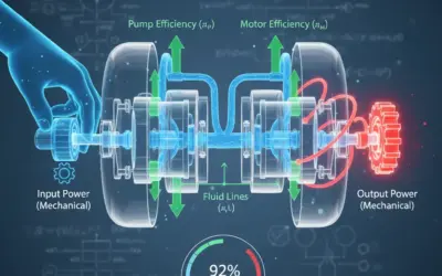
Context: The Hydrostatic Transmission (HST)A system that uses pressurized fluid to transmit power from a prime mover (like an engine) to a hydraulic motor (actuator)..
Hydrostatic transmissions (HSTs) are fundamental in mobile and industrial machinery, from excavators to ride-on lawnmowers. Understanding their efficiency is crucial for engineers to select components, predict performance, and manage energy consumption. This exercise will guide you through a complete performance analysis of a pump-motor pair, using real-world test data to find all component and system efficiencies.
Learning Note: This exercise will teach you how to break down a complex system's efficiency into its core components (volumetric and mechanical) and then combine them to find the overall system performance.
Learning Objectives
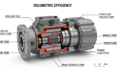
- Understand the difference between volumetricEfficiency loss due to internal fluid leakage., mechanicalEfficiency loss due to friction in moving parts., and global efficiencyThe total combined efficiency; the product of volumetric and mechanical efficiencies..
- Calculate the individual efficiencies for a hydraulic pump and motor.
- Combine pump and motor efficiencies to find the total global efficiency of the transmission.
- Apply standard US fluid power formulas (using GPM, PSI, in-lbf, and HP).
Problem Data
Test Bench Setup
| Component | Specification |
|---|---|
| Prime Mover | Electric Motor, 1800 RPM (Constant) |
| Hydraulic Fluid | ISO VG 46 @ 140°F (60°C) |
| System Type | Closed-Loop Circuit |
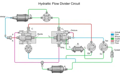
Simplified HST Schematic
| Parameter | Symbol | Value | Unit |
|---|---|---|---|
| Pump Speed | \(N_{\text{p}}\) | 1800 | RPM |
| Pump DisplacementThe volume of fluid moved by a pump or motor in one full revolution (e.g., in³/rev or cc/rev). | \(D_{\text{p}}\) | 2.0 | in³/rev |
| Motor Displacement | \(D_{\text{m}}\) | 1.5 | in³/rev |
| System Pressure | \(P\) | 3000 | PSIPounds per Square Inch, a standard US unit for pressure. |
| Measured Pump Flow | \(Q_{\text{p,act}}\) | 14.8 | GPMGallons Per Minute, a standard US unit for fluid flow rate. |
| Measured Pump Input Torque | \(T_{\text{p,in}}\) | 1038 | in-lbfInch-pounds-force, a standard US unit for torque. |
| Measured Motor Output Torque | \(T_{\text{m,out}}\) | 666 | in-lbf |
| Measured Motor Speed | \(N_{\text{m,act}}\) | 2150 | RPM |
Questions to Solve
- Calculate the pump's theoretical flow (\(Q_{\text{p,th}}\)) and its volumetric efficiency (\(\eta_{\text{v,p}}\)).
- Calculate the pump's theoretical torque (\(T_{\text{p,th}}\)) and its mechanical efficiency (\(\eta_{\text{m,p}}\)).
- Calculate the pump's overall efficiency (\(\eta_{\text{g,p}}\)) and its input power (\(P_{\text{in,p}}\)) in Horsepower.
- Calculate the motor's theoretical speed (\(N_{\text{m,th}}\)) and its volumetric efficiency (\(\eta_{\text{v,m}}\)).
- Calculate the motor's theoretical torque (\(T_{\text{m,th}}\)) and its mechanical efficiency (\(\eta_{\text{m,m}}\)).
- Calculate the motor's overall efficiency (\(\eta_{\text{g,m}}\)) and the final system global efficiency (\(\eta_{\text{g,system}}\)).
Fundamentals of HST Efficiency
Efficiency in fluid power is the ratio of output power to input power. It's always less than 100% due to internal losses. We split these losses into two categories: volumetric and mechanical.
1. Volumetric Efficiency (\(\eta_{\text{v}}\))
This measures losses due to internal leakage (fluid slipping from the high-pressure side to the low-pressure side instead of doing useful work). It's the ratio of *actual flow* to *theoretical flow* (for a pump) or *actual speed* to *theoretical speed* (for a motor).
\[ \eta_{\text{v}} = \frac{\text{Actual Output (Flow/Speed)}}{\text{Theoretical Output (Flow/Speed)}} \]
2. Mechanical Efficiency (\(\eta_{\text{m}}\))
This measures losses due to friction (in bearings, pistons, gears, etc.). It's the ratio of *theoretical torque* required to *actual torque* applied. The formula is 'flipped' for pumps (input) vs. motors (output).
\[ \eta_{\text{m, pump}} = \frac{T_{\text{theoretical}}}{T_{\text{actual, in}}} \quad | \quad \eta_{\text{m, motor}} = \frac{T_{\text{actual, out}}}{T_{\text{theoretical}}} \]
3. Global (Overall) Efficiency (\(\eta_{\text{g}}\))
This is the total efficiency, accounting for both loss types. It's the product of the volumetric and mechanical efficiencies. It is the ultimate measure of performance.
\[ \eta_{\text{g}} = \eta_{\text{v}} \times \eta_{\text{m}} = \frac{P_{\text{out}}}{P_{\text{in}}} \]
Solution: Analysis of a Hydrostatic Piston-Pump/Motor Transmission
Question 1: Calculate the pump's theoretical flow (\(Q_{\text{p,th}}\)) and its volumetric efficiency (\(\eta_{\text{v,p}}\)).
Principle
Theoretical flow is the volume of fluid the pump *should* displace per unit time, assuming it's a perfect machine with zero leakage. We then compare this ideal value to the *actual* measured flow to find the volumetric efficiency.
Mini-Lesson
The theoretical flow rate (in GPM) is the pump's displacement (in cubic inches per revolution) multiplied by its speed (in RPM), divided by 231 (the number of cubic inches in one US gallon). Volumetric efficiency is simply the ratio of actual flow to this theoretical flow.
Strategy Note
Always start by calculating the theoretical values. They are your '100%' benchmark against which you'll measure all real-world performance. This first step tells us how much fluid is "lost" to internal leakage.
Standards
These calculations follow standard NFPA (National Fluid Power Association) and ISO 1219-1/2 formulas for fluid power components using US customary units.
Formula(s)
Here are the two formulas needed for this step.
Theoretical Flow (GPM)
Volumetric Efficiency
Assumptions
We assume the pump speed (\(N_{\text{p}}\)) and flow meter (\(Q_{\text{p,act}}\)) readings are accurate.
- Pump speed is constant.
- Fluid properties are stable.
Given Data
The key data from the problem for this step.
| Parameter | Symbol | Value | Unit |
|---|---|---|---|
| Pump Displacement | \(D_{\text{p}}\) | 2.0 | in³/rev |
| Pump Speed | \(N_{\text{p}}\) | 1800 | RPM |
| Measured Pump Flow | \(Q_{\text{p,act}}\) | 14.8 | GPM |
Tips
The number 231 is your best friend when converting between in³/rev & RPM and GPM. Don't forget it!
Pre-Calculation Diagram
This calculation focuses on the pump's kinematics (speed) and geometry (displacement) vs. its actual measured output flow.
Pump Flow Analysis
Calculation(s)
Here is the detailed breakdown of each calculation, showing how we substitute the values from our data tables into the formulas.
Step 1: Calculate Theoretical Flow
We start with the formula for theoretical flow. We then substitute the values for Pump Displacement (\(D_{\text{p}} = 2.0 \text{ in}^3/\text{rev}\)) and Pump Speed (\(N_{\text{p}} = 1800 \text{ RPM}\)).
The result shows that the pump should ideally move 15.58 Gallons Per Minute.
Step 2: Calculate Volumetric Efficiency
Next, we use the formula for volumetric efficiency. We substitute the Measured Pump Flow (\(Q_{\text{p,act}} = 14.8 \text{ GPM}\)) and our calculated Theoretical Flow (\(Q_{\text{p,th}} = 15.58 \text{ GPM}\)).
This means the pump is 95.0% efficient at moving fluid; 5.0% is lost to internal leakage.
Post-Calculation Diagram
We can now visualize the flow paths. The Theoretical Flow is the total, which splits into the useful Actual Flow and the "lost" Leakage Flow.
Pump Flow Distribution
Analysis
The theoretical flow is 15.58 GPM. A volumetric efficiency of 95.0% is a typical and reasonable value for a piston pump at this pressure. This means 5.0% of the fluid that *should* be pushed into the system is instead leaking internally from the high-pressure side to the low-pressure side.
Points of Caution
Always ensure the *actual* flow is in the numerator and the *theoretical* flow is in the denominator. The efficiency must be less than or equal to 100%.
Key Takeaways
This step shows how to quantify internal leakage losses.
- Formula: \( Q_{\text{th}} = (D \times N) / 231 \)
- Formula: \( \eta_{\text{v}} = Q_{\text{act}} / Q_{\text{th}} \)
Did You Know?
This "lost" flow (0.78 GPM) isn't truly "lost"—it just didn't make it out of the pump. It leaks past pistons and valve plates. This internal leakage is the primary source of heat generation in a hydraulic system at standby.
FAQ
Common questions about this step.
Final Result
Your Turn
Using our calculated \(Q_{\text{p,th}}\) of 15.58 GPM, what would the volumetric efficiency be if the measured flow was only 14.5 GPM?
Summary Card
Q1 Summary:
- Concept: Pump Theoretical Flow & Volumetric Efficiency.
- Formulas: \(Q_{\text{th}} = (D \times N) / 231\), \(\eta_{\text{v}} = Q_{\text{act}} / Q_{\text{th}}\).
- Result: \(Q_{\text{p,th}}\) = 15.58 GPM, \(\eta_{\text{v,p}}\) = 95.0%.
Question 2: Calculate the pump's theoretical torque (\(T_{\text{p,th}}\)) and its mechanical efficiency (\(\eta_{\text{m,p}}\)).
Principle
Now we analyze the *torque* side. Theoretical torque is the ideal torque needed to displace the fluid *if there was zero friction*. We compare this ideal value to the *actual* torque we had to supply to find the mechanical efficiency.
Mini-Lesson
Mechanical efficiency (\(\eta_{\text{m}}\)) quantifies losses due to friction (bearings, piston-to-barrel, gears, etc.). The actual torque required to turn the pump (\(T_{\text{p,in}}\)) will always be higher than the theoretical torque (\(T_{\text{p,th}}\)) needed just to move the fluid. This "extra" torque is the friction loss.
Strategy Note
It's common to confuse the numerator and denominator. Remember: for a pump (an input device), you must put *more* work in than you get out. Therefore, the *actual* input torque is the larger number and goes in the denominator. The efficiency must be < 100%.
Standards
These calculations follow standard NFPA (National Fluid Power Association) and ISO 1219-1/2 formulas for fluid power components using US customary units. The theoretical torque formula is universal.
Formula(s)
Theoretical Torque (in-lbf)
Mechanical Efficiency (Pump)
Assumptions
We assume the pressure reading (\(P\)) and torque sensor (\(T_{\text{p,in}}\)) readings are accurate.
- Pressure is constant and stable.
- No torque losses between the sensor and the pump shaft.
Given Data
| Parameter | Symbol | Value | Unit |
|---|---|---|---|
| Pump Displacement | \(D_{\text{p}}\) | 2.0 | in³/rev |
| System Pressure | \(P\) | 3000 | PSI |
| Measured Pump Input Torque | \(T_{\text{p,in}}\) | 1038 | in-lbf |
Tips
The constant \(2\pi\) (approx 6.283) is the "231" of torque calculations. It converts from linear force (from \(P \times D\)) to rotational torque. Remember \(D\) is *volume per revolution* and \(2\pi\) is *radians per revolution*.
Pre-Calculation Diagram
This calculation focuses on the rotational forces (torques) acting on the pump shaft.
Pump Torque Analysis
Calculation(s)
Here is the detailed breakdown of each calculation, showing how we substitute the values from our data tables into the formulas.
Step 1: Calculate Theoretical Torque
We use the formula for theoretical torque. We substitute Pump Displacement (\(D_{\text{p}} = 2.0 \text{ in}^3/\text{rev}\)) and System Pressure (\(P = 3000 \text{ PSI}\)). We use \(2\pi \approx 6.283\).
This is the ideal torque (954.9 in-lbf) required just to move the fluid, assuming zero friction.
Step 2: Calculate Mechanical Efficiency
Now, we use the formula for pump mechanical efficiency. We substitute our calculated Theoretical Torque (\(T_{\text{p,th}} = 954.9 \text{ in-lbf}\)) and the Measured Pump Input Torque (\(T_{\text{p,in}} = 1038 \text{ in-lbf}\)).
The pump is 92.0% mechanically efficient. 8.0% of the input torque is lost to friction.
Post-Calculation Diagram
We can visualize the torque components. The total input torque is split between the useful theoretical torque and the torque lost to friction.
Pump Torque Distribution
Analysis
A mechanical efficiency of 92.0% is a very good value for a piston pump at this pressure. This means 8.0% of the input torque is "wasted" just to overcome the internal friction of the pump's rotating group. This friction loss (83.1 in-lbf) also generates significant heat.
Points of Caution
For a pump, mechanical efficiency is \(\frac{T_{\text{th}}}{T_{\text{in}}}\). The actual input torque must *always* be larger than the theoretical torque to overcome friction. The efficiency will be < 100%.
Key Takeaways
This step shows how to quantify internal friction losses.
- Formula: \( T_{\text{th}} = (D \times P) / 2\pi \)
- Formula: \( \eta_{\text{m,p}} = T_{\text{th}} / T_{\text{in}} \)
Did You Know?
This "lost" torque (83.1 in-lbf) is primarily due to hydro-mechanical friction (pistons sliding in bores) and viscous friction in the bearings. As fluid viscosity *decreases* (gets thinner) with heat, this friction loss often goes down slightly.
FAQ
Common questions about this step.
Final Result
Your Turn
Using our calculated \(T_{\text{p,th}}\) of 954.9 in-lbf, what would the mechanical efficiency be if the measured *input* torque was 1100 in-lbf?
Summary Card
Q2 Summary:
- Concept: Pump Theoretical Torque & Mechanical Efficiency.
- Formulas: \(T_{\text{th}} = (D \times P) / 2\pi\), \(\eta_{\text{m,p}} = T_{\text{th}} / T_{\text{in}}\).
- Result: \(T_{\text{p,th}}\) = 954.9 in-lbf, \(\eta_{\text{m,p}}\) = 92.0%.
Question 3: Calculate the pump's overall efficiency (\(\eta_{\text{g,p}}\)) and its input power (\(P_{\text{in,p}}\)) in Horsepower.
Principle
Overall (Global) efficiency is the product of the two other efficiencies. It tells us the total performance of the pump. Input power is the *actual* mechanical power supplied by the prime mover (electric motor), calculated using the *actual* input torque and speed.
Mini-Lesson
Global efficiency is the "bottom line" for the pump: \(\eta_{\text{g}} = \eta_{\text{v}} \times \eta_{\text{m}}\). Horsepower is a unit of power (work over time). The formula \(P_{\text{HP}} = (T \times N) / 63025\) is a direct conversion from torque (in-lbf) and speed (RPM) to Horsepower.
Strategy Note
This is the 'bottom line' for the pump. It answers two key questions: 1. "How much of my input power is actually converted to useful hydraulic power?" (Answer: \(\eta_{\text{g,p}}\)) and 2. "What size electric motor (in HP) do I need to run this pump at this condition?" (Answer: \(P_{\text{in,p}}\)).
Standards
Horsepower (HP) is a standard US unit of power. The constant 63025 is derived from \(33,000 \text{ ft-lbf/min} \times 12 \text{ in/ft} / (2\pi \text{ rad/rev})\). It is specific to Torque in *in-lbf* and Speed in *RPM*.
Formula(s)
Global Efficiency
Input Power (HP)
Assumptions
We assume our calculated efficiency values from Q1 and Q2 are correct and representative of the total losses.
Given Data
| Parameter | Symbol | Value |
|---|---|---|
| Volumetric Efficiency (from Q1) | \(\eta_{\text{v,p}}\) | 95.0% (or 0.950) |
| Mechanical Efficiency (from Q2) | \(\eta_{\text{m,p}}\) | 92.0% (or 0.920) |
| Measured Pump Input Torque | \(T_{\text{p,in}}\) | 1038 in-lbf |
| Pump Speed | \(N_{\text{p}}\) | 1800 RPM |
Tips
The constant 63025 is your best friend for calculating HorsepowerA standard US unit of power, commonly used for engines and motors. 1 HP = 33,000 ft-lbf/min. (HP) when you have torque in in-lbf and speed in RPM. A common shortcut for hydraulic power is \(P_{\text{HP}} = (P \times Q) / 1714\), where P is in PSI and Q is in GPM. You can use this to check your answer!
Pre-Calculation Diagram
A power flow diagram helps visualize this step. We are calculating the total mechanical power going *in* and the overall efficiency of the conversion to hydraulic power.
Pump Power Flow
Calculation(s)
Here is the detailed breakdown of each calculation, showing how we substitute the values from our data tables into the formulas.
Step 1: Calculate Global Efficiency
We multiply the two efficiencies we just found: Volumetric Efficiency (\(\eta_{\text{v,p}} = 0.950\)) and Mechanical Efficiency (\(\eta_{\text{m,p}} = 0.920\)).
The pump's total (overall) efficiency is 87.4%.
Step 2: Calculate Input Power
We use the Horsepower formula, substituting the *actual* Measured Pump Input Torque (\(T_{\text{p,in}} = 1038 \text{ in-lbf}\)) and Pump Speed (\(N_{\text{p}} = 1800 \text{ RPM}\)).
This shows that 29.65 Horsepower is required from the prime mover to run the pump under these conditions.
Analysis
The pump is 87.4% efficient overall. To produce the required hydraulic power (Pressure of 3000 PSI and Flow of 14.8 GPM), we must supply 29.65 HP of mechanical power to its input shaft. The "lost" power (\(29.65 - (29.65 \times 0.874) \approx 3.74 \text{ HP}\)) is converted directly into heat.
Points of Caution
To calculate *input* power, you must use the *actual measured input torque* (\(T_{\text{p,in}}\)), not the theoretical torque. Using \(T_{\text{p,th}}\) would give you the *ideal* power, which isn't what the electric motor actually has to supply.
Key Takeaways
This step combines losses and finds the real power requirement.
- Formula: \( \eta_{\text{g}} = \eta_{\text{v}} \times \eta_{\text{m}} \)
- Formula: \( P_{\text{HP}} = (T \times N) / 63025 \)
Did You Know?
Let's check our answer with the hydraulic power formula: \(P_{\text{HP,out}} = (P \times Q_{\text{act}}) / 1714 = (3000 \times 14.8) / 1714 = 25.90 \text{ HP}\). Now, let's find the efficiency: \(\eta_{\text{g}} = P_{\text{out}} / P_{\text{in}} = 25.90 / 29.65 = 0.8735\), or 87.4%. The numbers match!
FAQ
...
Final Result
Your Turn
What is the output hydraulic power of the pump (in HP)? (Hint: \(P_{\text{out}} = P_{\text{in}} \times \eta_{\text{g,p}}\) or use the shortcut from "Le saviez-vous?")
Summary Card
Q3 Summary:
- Concept: Pump Global Efficiency & Input Power.
- Formulas: \(\eta_{\text{g}} = \eta_{\text{v}} \times \eta_{\text{m}}\), \(P_{\text{HP}} = (T \times N) / 63025\).
- Result: \(\eta_{\text{g,p}}\) = 87.4%, \(P_{\text{in,p}}\) = 29.65 HP.
Question 4: Calculate the motor's theoretical speed (\(N_{\text{m,th}}\)) and its volumetric efficiency (\(\eta_{\text{v,m}}\)).
Principle
Now we analyze the motor. This is the reverse of the pump's flow calculation. We know the *actual flow* from the pump (\(Q_{\text{p,act}}\)) is the *input flow* to the motor. Theoretical speed is the speed the motor *should* turn at with this flow, assuming no leakage.
Mini-Lesson
The formula for theoretical speed is a rearrangement of the pump's flow formula: \(N_{\text{th}} = (Q_{\text{in}} \times 231) / D_{\text{m}}\). For a motor, volumetric efficiency is the ratio of *actual measured speed* to the *theoretical speed*. \(\eta_{\text{v,m}} = N_{\text{act}} / N_{\text{th}}\). This accounts for the internal leakage *within the motor*.
Strategy Note
This is the first half of the motor analysis. We're finding out how much of the flow (14.8 GPM) is "lost" to leakage inside the motor, and how much is actually used to create rotation. The actual speed will *always* be lower than the theoretical speed.
Standards
Again, these are standard NFPA and ISO formulas. The logic is simply inverted from the pump calculation. The same conversion constant, 231, is used.
Formula(s)
Theoretical Speed (RPM)
Volumetric Efficiency (Motor)
Assumptions
We assume the flow from the pump (\(Q_{\text{p,act}}\)) is the exact flow entering the motor (\(Q_{\text{in}}\)). This is true for a closed-loop system, neglecting tiny (and complex) fluid compression effects.
- \(Q_{\text{in, motor}} = Q_{\text{p,act}}\)
Given Data
| Parameter | Symbol | Value | Unit |
|---|---|---|---|
| Motor Input Flow (from pump) | \(Q_{\text{in}}\) | 14.8 | GPM |
| Motor Displacement | \(D_{\text{m}}\) | 1.5 | in³/rev |
| Measured Motor Speed | \(N_{\text{m,act}}\) | 2150 | RPM |
Tips
Don't get confused. For the pump, we used *speed* to find *theoretical flow*. For the motor, we use *flow* to find *theoretical speed*. It's the same formula, just solving for a different variable.
Pre-Calculation Diagram
We are now looking at the motor. Flow goes in, speed comes out. We want to find the ideal speed.
Motor Speed Analysis
Calculation(s)
Here is the detailed breakdown of each calculation, showing how we substitute the values from our data tables into the formulas.
Step 1: Calculate Theoretical Speed
We rearrange the flow formula to solve for speed. We substitute the Motor Input Flow (\(Q_{\text{in}} = 14.8 \text{ GPM}\)) and the Motor Displacement (\(D_{\text{m}} = 1.5 \text{ in}^3/\text{rev}\)).
The motor should ideally be spinning at 2279.2 RPM given the flow it's receiving.
Step 2: Calculate Volumetric Efficiency
We use the formula for motor volumetric efficiency. We substitute the Measured Motor Speed (\(N_{\text{m,act}} = 2150 \text{ RPM}\)) and our calculated Theoretical Speed (\(N_{\text{m,th}} = 2279.2 \text{ RPM}\)).
The motor is 94.3% volumetrically efficient. 5.7% of the incoming flow is lost to internal leakage (slip) and does not contribute to rotation.
Post-Calculation Diagram
We can visualize the speed. The flow *should* have created 2279.2 RPM, but due to internal leakage ("slip"), the actual speed is only 2150 RPM.
Motor Speed Distribution
Analysis
The motor *should* be spinning at 2279.2 RPM with 14.8 GPM of flow. However, it's only spinning at 2150 RPM. This means it has a volumetric efficiency of 94.3%. The "lost" speed (129.2 RPM) is because 5.7% of the incoming flow is leaking internally rather than being used to turn the motor's shaft.
Points of Caution
For a motor, volumetric efficiency is \(\frac{N_{\text{act}}}{N_{\text{th}}}\). The actual speed will always be *less* than the theoretical speed because some input flow leaks internally instead of turning the motor.
Key Takeaways
Motor volumetric losses are measured as a loss of speed.
- Formula: \( N_{\text{th}} = (Q_{\text{in}} \times 231) / D_{\text{m}} \)
- Formula: \( \eta_{\text{v,m}} = N_{\text{act}} / N_{\text{th}} \)
Did You Know?
The motor's displacement (1.5 in³/rev) is smaller than the pump's (2.0 in³/rev). This is a "speed up" drive. The motor's theoretical speed (2279.2 RPM) is higher than the pump's input speed (1800 RPM). This is a common design choice in HSTs.
FAQ
...
Final Result
Your Turn
If the motor's displacement (\(D_{\text{m}}\)) was 1.8 in³/rev, what would its theoretical speed be (using the same 14.8 GPM input)?
Summary Card
Q4 Summary:
- Concept: Motor Theoretical Speed & Volumetric Efficiency.
- Formulas: \(N_{\text{th}} = (Q_{\text{in}} \times 231) / D_{\text{m}}\), \(\eta_{\text{v,m}} = N_{\text{act}} / N_{\text{th}}\).
- Result: \(N_{\text{m,th}}\) = 2279.2 RPM, \(\eta_{\text{v,m}}\) = 94.3%.
Question 5: Calculate the motor's theoretical torque (\(T_{\text{m,th}}\)) and its mechanical efficiency (\(\eta_{\text{m,m}}\)).
Principle
This is the partner to the motor's speed calculation. We find the ideal torque the motor *should* produce based on its displacement and the system pressure. We then compare this to the *actual* measured output torque to find the mechanical efficiency.
Mini-Lesson
The theoretical torque formula is identical to the pump's, using the motor's displacement: \(T_{\text{th}} = (D_{\text{m}} \times P) / 2\pi\). However, the mechanical efficiency formula is inverted: \(\eta_{\text{m,m}} = T_{\text{m,out}} / T_{\text{m,th}}\). This is because friction *reduces* the available output torque.
Strategy Note
This is the second half of the motor analysis. We're finding out how much of the "ideal" torque is lost to friction inside the motor. The actual torque at the shaft will *always* be lower than the theoretical torque generated by the pressure.
Standards
Again, these are standard NFPA and ISO formulas. The key is applying the efficiency concept correctly (output/input). For motor mechanical efficiency, the *input* is theoretical torque and the *output* is actual torque.
Formula(s)
Theoretical Torque (in-lbf)
Mechanical Efficiency (Motor)
Assumptions
We assume the pressure (\(P\)) is constant and the torque sensor (\(T_{\text{m,out}}\)) is accurate.
Given Data
| Parameter | Symbol | Value | Unit |
|---|---|---|---|
| Motor Displacement | \(D_{\text{m}}\) | 1.5 | in³/rev |
| System Pressure | \(P\) | 3000 | PSI |
| Measured Motor Output Torque | \(T_{\text{m,out}}\) | 666 | in-lbf |
Tips
The theoretical torque calculation is identical to the pump's, just with the motor's displacement. This is a very common source of error: always double-check you are using \(D_{\text{m}}\) (1.5) and not \(D_{\text{p}}\) (2.0)!
Pre-Calculation Diagram
Here, pressure creates a theoretical torque, which is reduced by friction to produce the final, actual output torque.
Motor Torque Analysis
Calculation(s)
Here is the detailed breakdown of each calculation, showing how we substitute the values from our data tables into the formulas.
Step 1: Calculate Theoretical Torque
We use the same theoretical torque formula as the pump, but with the *motor's* displacement. We substitute Motor Displacement (\(D_{\text{m}} = 1.5 \text{ in}^3/\text{rev}\)) and System Pressure (\(P = 3000 \text{ PSI}\)).
This is the ideal torque (716.2 in-lbf) the motor should produce from the system pressure, assuming zero friction.
Step 2: Calculate Mechanical Efficiency
We use the formula for motor mechanical efficiency. We substitute the Measured Motor Output Torque (\(T_{\text{m,out}} = 666 \text{ in-lbf}\)) and our calculated Theoretical Torque (\(T_{\text{m,th}} = 716.2 \text{ in-lbf}\)).
The motor is 93.0% mechanically efficient. 7.0% of the theoretical torque is lost to its own internal friction.
Post-Calculation Diagram
We can visualize the motor's torque. The ideal torque is split between the useful output torque and the torque lost to internal friction.
Motor Torque Distribution
Analysis
The motor *should* be producing 716.2 in-lbf of torque. However, due to internal friction, it only outputs 666 in-lbf. This gives a mechanical efficiency of 93.0%. The "lost" 50.2 in-lbf of torque is converted to heat by friction.
Points of Caution
For a motor, mechanical efficiency is \(\frac{T_{\text{out}}}{T_{\text{th}}}\). The actual output torque will always be *less* than theoretical due to internal friction losses. This is the reverse of the pump calculation!
Key Takeaways
Motor mechanical losses are measured as a loss of output torque.
- Formula: \( T_{\text{th}} = (D \times P) / 2\pi \)
- Formula: \( \eta_{\text{m,m}} = T_{\text{out}} / T_{\text{th}} \)
Did You Know?
The mechanical efficiency of a motor (93.0%) is often slightly higher than its pump counterpart (92.0%), even if they are built similarly. This is because the high pressure helps to *lubricate* some components in a motor, whereas it can *increase* forces (and friction) in a pump.
FAQ
...
Final Result
Your Turn
If the system pressure was only 2500 PSI, what would the theoretical torque be?
Summary Card
Q5 Summary:
- Concept: Motor Theoretical Torque & Mechanical Efficiency.
- Formulas: \(T_{\text{th}} = (D \times P) / 2\pi\), \(\eta_{\text{m,m}} = T_{\text{out}} / T_{\text{th}}\).
- Result: \(T_{\text{m,th}}\) = 716.2 in-lbf, \(\eta_{\text{m,m}}\) = 93.0%.
Question 6: Calculate the motor's overall efficiency (\(\eta_{\text{g,m}}\)) and the final system global efficiency (\(\eta_{\text{g,system}}\)).
Principle
Finally, we combine all our findings. We find the motor's total efficiency just like we did for the pump. Then, we multiply the pump's global efficiency by the motor's global efficiency to find the total efficiency of the entire transmission, from input shaft to output shaft.
Mini-Lesson
The motor's global efficiency is its total performance: \(\eta_{\text{g,m}} = \eta_{\text{v,m}} \times \eta_{\text{m,m}}\). The system's total efficiency is the product of the efficiencies of all components in series. Power is lost in the pump, and then *more* power is lost in the motor.
Strategy Note
This is the final, most important answer. It tells you, for every 1 HP you put *into* the pump, how much HP you *get out* of the motor. The difference is all lost to heat (from leakage and friction in *both* units). This is why managing heat is so critical in HSTs.
Standards
This is a standard principle of systems engineering: the total efficiency of a series system is the product of the efficiencies of its individual components.
Formula(s)
Global Efficiency (Motor)
System Global Efficiency
Assumptions
We assume all previous calculations are correct. We also assume there are no significant pressure or flow losses in the hoses connecting the pump and motor. In a real system, these "line losses" would also be factored in, further reducing the total efficiency.
Given Data
| Parameter | Symbol | Value |
|---|---|---|
| Pump Global Efficiency (from Q3) | \(\eta_{\text{g,p}}\) | 87.4% (or 0.874) |
| Motor Volumetric Eff. (from Q4) | \(\eta_{\text{v,m}}\) | 94.3% (or 0.943) |
| Motor Mechanical Eff. (from Q5) | \(\eta_{\text{m,m}}\) | 93.0% (or 0.930) |
Tips
A quick check: System efficiency \(\eta_{\text{g,system}}\) MUST be lower than the efficiency of *any* single component. If your answer is > 87.4% or > 87.7%, you've made a mistake. Losses always accumulate.
Pre-Calculation Diagram
This is the complete power flow for the entire system, from the input shaft of the pump to the output shaft of the motor.
Total System Power Flow
Calculation(s)
Here is the detailed breakdown of each calculation, showing how we substitute the values from our data tables into the formulas.
Step 1: Calculate Motor's Global Efficiency
We multiply the motor's two efficiencies: Motor Volumetric Efficiency (\(\eta_{\text{v,m}} = 0.943\)) and Motor Mechanical Efficiency (\(\eta_{\text{m,m}} = 0.930\)).
The motor's total (overall) efficiency is 87.7%.
Step 2: Calculate System Global Efficiency
Finally, we multiply the global efficiency of the pump (\(\eta_{\text{g,p}} = 0.874\)) by the global efficiency of the motor (\(\eta_{\text{g,m}} = 0.877\)) to find the total system efficiency.
The total efficiency of the entire transmission, from input shaft to output shaft, is 76.7%.
Post-Calculation Diagram
Here is the final power flow diagram, or Sankey diagram, showing all power values and losses at each stage.
Completed System Power Flow
Analysis
This is the final answer. The total system efficiency is 76.7%. This means of the 29.65 HP of electrical power going into the pump's shaft, only \(29.65 \times 0.767 = \) 22.74 HP is available at the motor's output shaft. The remaining 6.9 HP is lost as heat due to leakage and friction in both components.
Points of Caution
A common mistake is to *average* the efficiencies. This is incorrect. Efficiencies in a series system are *multiplied*. Averaging (87.4% and 87.7%) would give 87.55%, which is wrong and over-optimistic.
Key Takeaways
The total efficiency of a system is the product of the efficiencies of its components.
- Formula: \( \eta_{\text{g,system}} = \eta_{\text{g,pump}} \times \eta_{\text{g,motor}} \)
Did You Know?
This 76.7% efficiency is actually quite high. A typical gear-pump-to-gear-motor system might be 60-65%. This high efficiency is why piston-based HSTs are the standard for high-power mobile equipment, as the 10-15% efficiency gain saves a huge amount of fuel over the machine's lifetime.
FAQ
...
Final Result
Your Turn
Based on our findings, what is the final output power (in HP) at the motor shaft? (Hint: \(P_{\text{out}} = P_{\text{in,p}} \times \eta_{\text{g,system}}\) or use the FAQ method!)
Summary Card
Q6 Summary:
- Concept: Motor & System Global Efficiency.
- Formulas: \(\eta_{\text{g,m}} = \eta_{\text{v,m}} \times \eta_{\text{m,m}}\), \(\eta_{\text{g,system}} = \eta_{\text{g,p}} \times \eta_{\text{g,m}}\).
- Result: \(\eta_{\text{g,m}}\) = 87.7%, \(\eta_{\text{g,system}}\) = 76.7%.
Interactive Tool: Pump Efficiency Simulator
This simulator models the ideal pump from our exercise (\(D_{\text{p}} = 2.0 \text{ in}^3/\text{rev}\)). Use the sliders to see how theoretical power, flow, and torque change with speed and pressure.
Input Parameters
Theoretical Results
Final Quiz: Test Your Knowledge
1. Volumetric efficiency (\(\eta_v\)) is a measure of losses due to...
2. Mechanical efficiency (\(\eta_m\)) is a measure of losses due to...
3. A pump has a theoretical torque (\(T_{th}\)) of 500 in-lbf and a measured input torque (\(T_{in}\)) of 550 in-lbf. What is its mechanical efficiency?
4. A motor has a theoretical speed (\(N_{th}\)) of 1000 RPM and a measured actual speed (\(N_{act}\)) of 950 RPM. What is its volumetric efficiency?
5. If a pump's global efficiency is 90% and its motor's global efficiency is 90%, what is the total system efficiency?
Glossary
- Displacement (D)
- The volume of fluid moved by a pump or motor in one full revolution (e.g., in³/rev or cc/rev).
- Global Efficiency (\(\eta_g\))
- The total efficiency of a component, calculated as \(\eta_{\text{v}} \times \eta_{\text{m}}\). It is the ratio of power out to power in.
- GPM
- Gallons Per Minute, a standard US unit for fluid flow rate (1 GPM = 231 in³/min).
- Horsepower (HP)
- A standard US unit of power, commonly used for engines and motors. 1 HP = 33,000 ft-lbf/min = 63,025 in-lbf/RPM.
- Hydrostatic Transmission (HST)
- A power transmission system that uses a closed-loop fluid circuit (pump and motor) to transfer rotational energy.
- in-lbf
- Inch-pounds-force, a standard US unit for torque.
- Mechanical Efficiency (\(\eta_m\))
- The ratio of theoretical torque to actual torque, representing losses due to friction.
- PSI
- Pounds per Square Inch, a standard US unit for pressure.
- Volumetric Efficiency (\(\eta_v\))
- The ratio of actual fluid flow to theoretical fluid flow, representing losses due to internal leakage.

0 Comments